Content .. 1124 1125 1126 1127 ..
Isuzu Amigo / Axiom / Trooper / Rodeo / VehiCross. Manual - part 1126
3F–34
INTELLIGENT SUSPENSION
Removal
1. Disconnect the battery ground cable.
2. Disconnect the connector from the harness and
remove the connector from the bracket.
3. Remove the clip.
View B
450RY00005
EndOFCallout
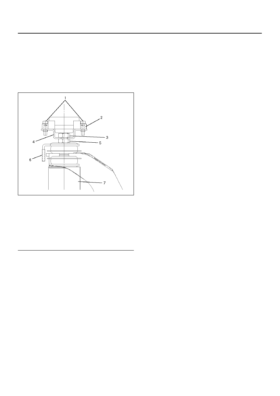
1. Remove 2 screws.
2. Disconnect the actuator.
3. Remove the nut (3).
4. Disconnect bracket.
5. Remove the nut (5).
6. Disconnect the washer.
7. Remove the shock absorber.
Refer to Shock Absorber in this section.
Inspection and Repair
Refer to shock Abosorber in this section.
Installation
1. Install the shock absorber.
Refer to Shock Absorber in this section.
2. Install the washer and nut (5), then tighten it to the
specified torque.
Torque: 15N·m (11 lb ft)
3. Install the bracket and nut (3), then tighten it to the
specified torque.
Torque: 39N·m (29 lb ft)
NOTE: Fix the lower nut with wrench not to turn and
tighten upper nut.
4. Fit the top of the shock absorber rod in the
connection part of the actuator.
NOTE:
The mating section is width fitting across flats.
If these normally fit, the distance between the
actuator lower face and the bracket upper face is
about 1 mm.
5. Install 2 screws then tighten it to the specified
torque.
3 N·m (26 lbin)
6. Connect the connector to the harness and insert the
connector to the bracket.
7. Connect the actuator harness with the clip.
8. Connect the battery ground cable.
Legend
(1) Screw
(2) Actuator
(3) Nut
(4) Bracket
(5) Nut
(6) Washer
(7) Shock Absorber