Isuzu Amigo / Axiom / Trooper / Rodeo / VehiCross. Manual - part 113


  Index      Isuzu     Isuzu Amigo / Axiom / Trooper / Rodeo / VehiCross - service repair manual 1999-2002 year


Search            


Content   ..  111  112  113  114   ..


Isuzu Amigo / Axiom / Trooper / Rodeo / VehiCross. Manual - part 113


DRIVE LINE CONTROL SYSTEM (TOD)

4B2–70

Chart B–1

The TOD switch A circuit wires are broken or short-circuited to the GND

Function of circuit

Fail condition

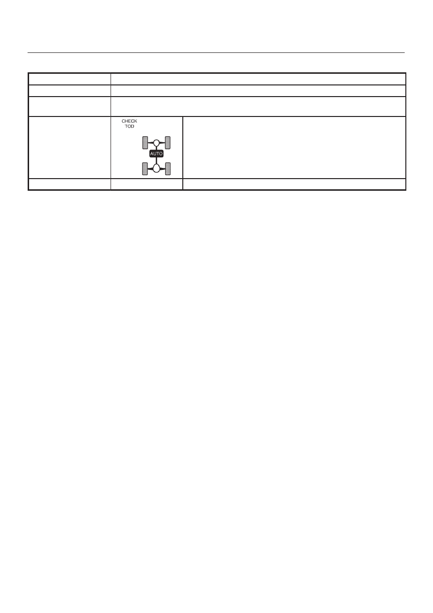
Even after the TOD switch position is selected from TOD to 2H, the indicator lamp status

is not changed.

Indicator lamp state

TOD switch position

2H

4B2–71

DRIVE LINE CONTROL SYSTEM (TOD)

D04R200022

DRIVE LINE CONTROL SYSTEM (TOD)

4B2–72

Step

Action

Yes

No

1

1. Turn on the starter switch.

When the TOD switch is selected to the TOD position, is 0V
observed between terminal 30 and 47, and 43 and 47? Does the
voltage between the terminals 7 and 47, 19 and 47, and 8 and 47
comply with the TOD mode in the following table?

Go to 

Step 2

Repair the TOD

switch circuit.

Go to 

Step 4

2

When the TOD switch is selected to the 2H position, is 12 V
observed between terminals 30 and 47 and is 0V observed
between terminal 43 and 47? Does the voltage between the
terminals 7 and 47, 19 and 47, and 8 and 47 comply with the 2H
mode is the following table?

Go to 

Step 3

Repair the TOD

switch circuit.

Go to 

Step 4

3

When the TOD switch is selected to the 4L position, is 0V
observed between terminals 30 and 47 and is 12V observed
between terminal 43 and 47? Does the voltage between terminals
7 and 47, 19 and 47, and 8 and 47 comply with the 4L mode in the
following table?

The phenomenon

is not

reproduced.

Refer to 

“Trouble

intermittently

observed”.

Repair the TOD

switch circuit.

Go to 

Step 4

4

Check that all the parts are mounted.

Is this step complete?

Verify the repair.

Return to Step 4

Table: Indicator Voltage

Unit: V

TOD

switch

Terminals measured

switch

mode

Front 7

and 47

AUTO 19

and 47

Rear 8 and

47

2H

8.0 

 14.5

8.0 

 14.5

0

TOD

0

0

0

4L

0

8.5 

 14.5

0

4B2–73

DRIVE LINE CONTROL SYSTEM (TOD)

Chart B–2

The TOD switch A circuit is shorted to battery.

Function of circuit

Fail condition

Even after the transfer mode is selected from 2H to TOD, the indicator lamp state does

not change.

Indicator lamp state

TOD switch position

TOD


Content   ..  111  112  113  114   ..