Isuzu Amigo / Axiom / Trooper / Rodeo / VehiCross. Manual - part 114
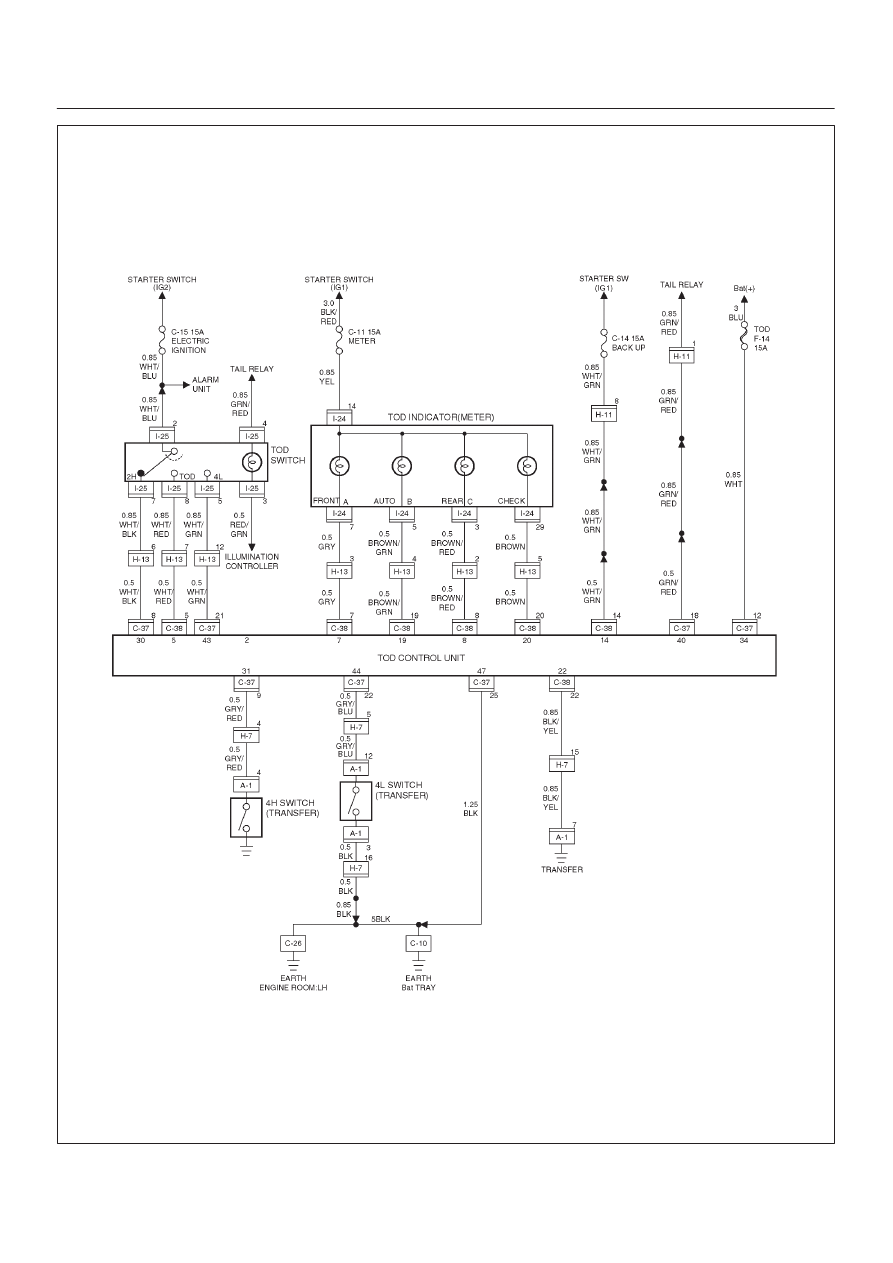
DRIVE LINE CONTROL SYSTEM (TOD)
4B2–74
D04R200022
Index Isuzu Isuzu Amigo / Axiom / Trooper / Rodeo / VehiCross - service repair manual 1999-2002 year
|
|
|
DRIVE LINE CONTROL SYSTEM (TOD) 4B2–74 D04R200022 |