Isuzu Amigo / Axiom / Trooper / Rodeo / VehiCross. Manual - part 91


  Index      Isuzu     Isuzu Amigo / Axiom / Trooper / Rodeo / VehiCross - service repair manual 1999-2002 year


Search            


Content   ..  89  90  91  92   ..


Isuzu Amigo / Axiom / Trooper / Rodeo / VehiCross. Manual - part 91


4A2–22

DIFFERNTIAL (REAR)

425RW018

Preload should be at 1.0 to 1.6 N·m (8 to 14 in lbs.)
on new bearings, or 0.46 to 0.69 N·m (4 to 6 in lbs.)
for used bearings.

D

If the preload torque is below the preloads given
above, continue torquing the nut in small
increments. Check the preload after each
tightening. Each tightening increases the bearing
preload by several pounds. If the bearing preload is
exceeded, the pinion will have to be removed, and a
new collapsible spacer installed.

D

Once a preload of 1.0 to 1.4 N·m (8 to 12 in lbs.)
has been obtained, rotate the pinion several times
to assure that the bearings have seated. Recheck
the preload, and adjust if necessary.

Determination of Backlash & Preload
Shims

1. Install master side bearings onto the case.
2. Install differential assembly into the carrier.
3. Install the bearing cap and finger tight bolts.
4. Set up the dial indicator.
5. Force the differential assembly away from the pinion

gear until it is completely seated against the cross
bore face of the carrier.

6. With force still applied to the differential case, place

the tip of dial indicator on a machined surface of the
differential case, if available, or on the head of a ring
gear screw, and set the indicator at zero(0).

7. Force the ring gear to mesh with the pinion gear. Rock

the ring gear slightly to make sure the gear teeth are
meshed. Repeat this procedure several times until
the same reading is obtained each time. Be sure the
indicator reads zero(0) each time the ring gear is
forced back into contact with the cross bore face. This
reading will be the necessary amount of shims to be
placed between the differential case and side bearing
cone on the ring gear side.

8. The remaining amount of shims, which is the

difference between the overall found in step 6 of Side
Bearing Pre-load Adjustment and step(7) above,
should be placed on the other side of the differential
case, plus additional 0.38 mm (0.015 in) for obtaining
preload and backlash.

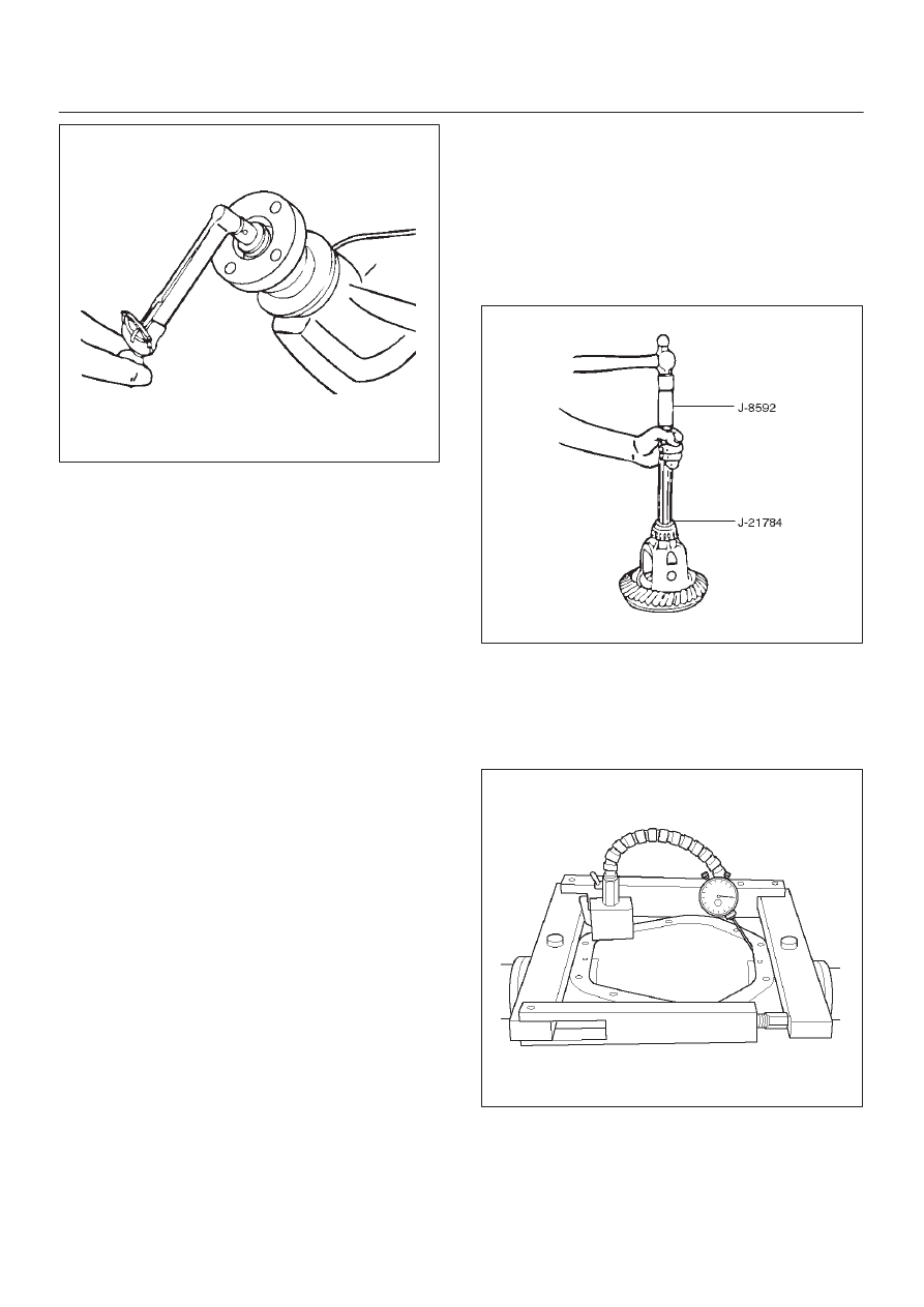
9. Place the required amount of shims on each hub as

determined in the previous steps and assemble side
bearing cone by using installer J–21784 and handle
J–8592.

425RW022

10. Total torque to rotate — Increase of pinion torque to

rotate due to differential case assembly shall not
exceed 3.4 N·m (30 in lbs.) divided by the gear ratio.

11. Assembly the spreader J–24385–B and indicator to

the carrier as shown in figure. Spread the carrier
0.5 mm (0.02 in) for differential installation.

420RW004

CAUTION: Do not spread the carrier over 0.5 mm
(0.02 in).

12. Remove the indicator.

DIFFERENTIAL (REAR)

4A2–23

Backlash Adjustment

1. Install the differential case assembly and bearing

caps.

2. Rotate the case several times to seat the bearings.
3. Remove the spreader.
4. Install the side bearing cap bolts.

Tighten side bearing cap bolts
Torque: 108 N·m (80 lb ft)

5. Install a dial indicator to the case using a magnetic

base.

6. Place the indicator stem at the heel end of a tooth.

D

Set the dial indicator so that the stem is in line with
the gear rotation and perpendicular to the tooth
angle.

425RS087

7. Check and record the backlash at three points around

the ring gear.

D

The pinion must be held stationary when checking
backlash.

D

The backlash should be the same at each point
within 0.07 mm (0.003 in). If the backlash varies
more than 0.07 mm (0.003 in), check for burrs, a
distorted case flange, or uneven bolting conditions.

8. Backlash at the minimum lash point measured should

be between 0.13 and 0.20 mm (0.005 and 0.008 in)
for all new gear sets.

9. If the backlash is not  within specifications, move the

ring gear in or out from the pinion by increasing the
thickness of one shims, and decreasing the thickness
of the other shim by the same amount.
This will maintain the correct rear axls side bearing
preload.

D

Moving 0.05 mm (0.002 in) worth of shim from one
side of the differential to the other will change the
backlash adjustment by 0.03 mm (0.001 in).

10. After obtaining correct tooth contact described in

later, install ABS speed sensor.

11. Install the cover with sealant.

Torque: 40 N·m (30 lb ft)

12. Fill the axle lubricant.

Gear Tooth Pattern Check

Checking the ring gear to pinion tooth pattern is to be
done only after setting up the axle according to the
methods in this section. The pattern check is NEVER to
be used as an initial check, or instead of checking pinion
depth and backlash adjustments.
This check is only to be verify the correct adjustment of
the gear set after set up.

425RS038

Legend

(1) Heel
(2) Toe
(3) Concave Side (Coast)
(4) Convex Side (Drive)

1. Wipe all oil out of the carrier, and carefully clean each

tooth of the ring gear.

2. Use gear marking compound 1052351 or equivalent

and apply this mixture sparingly to all ring gear teeth,
using a medium-stiff brush. When properly used, the
area of pinion tooth contact will be visible when hand
load is applied.

3. Tighten the bearing cap bolts to the specified torque.
4. Expand the brake shoes until a torque of 54 to 68 N·m

(40 to 50 lb ft.) is required to turn the pinion. A test
made without loading the gears will not give a
satisfactory pattern. Turn the pinion flange with a
wrench so that the ring gear rotates one full
revolution, then reverse the rotation so that the ring
gear rotates one revolution in the opposite direction.

5. Observe the pattern on the ring gear teeth and

compare this with figure.

4A2–24

DIFFERNTIAL (REAR)

425RS039

Adjustments Affecting Tooth Contact

Two adjustments can be made which will affect tooth
contact pattern: backlash, and the position of the drive
pinion in the case. The effects of bearing preloads are not
readily apparent on head loaded tooth contact pattern
tests; however, these adjustments should be within
specifications before proceeding with backlash and drive
pinion adjustments.
The position of the drive pinion is adjusted by increasing
or decreasing the distance between the pinion head and
the centerline of the ring gear.
Decreasing the distance will move the pinion closer to the
centerline of the ring gear. Increasing the distance will
move the pinion farther away from the centerline of the
ring gear.
Backlash is adjusted by means of the side bearing
adjusting shims which move the entire case and ring gear
assembly closer to, or farther from, the drive pinion. (The
adjusting shims are also used to set side bearing
preload.)
If the thickness of the right shim is increased (along with
decreasing the left shim thickness), backlash will
increase.
The backlash will decrease if the left shim thickness is
increased (along with a decrease in right shim thickness).

DIFFERENTIAL (REAR)

4A2–25

Differential Case Assembly

Disassembled View

425RW014

Legend

(1) Thrust Washer (for Pinion Gear)
(2) Pinion Mate Gear
(3) Thrust Washer(for Side Gear)
(4) Side Gear

(5) Differential Shaft
(6) Lock Pin
(7) Bolt
(8) Differential Case


Content   ..  89  90  91  92   ..