Isuzu Amigo / Axiom / Trooper / Rodeo / VehiCross. Manual - part 92
4A2–26
DIFFERNTIAL (REAR)
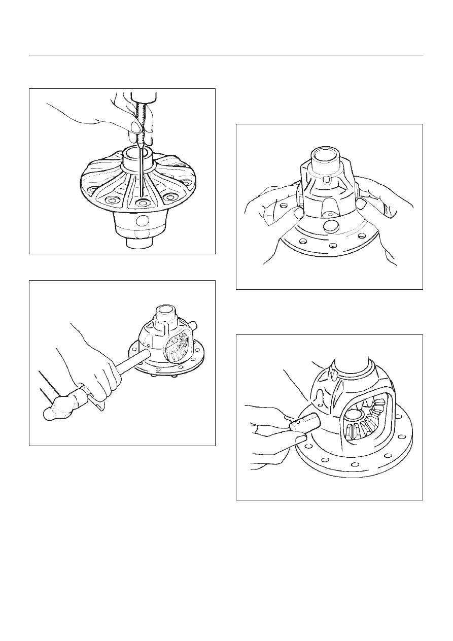
Disassembly
1. Remove lock pin using a small drift.
425RS098
2. Remove the differential shaft by using a soft metal rod
and a hammer.
425RS043
3. Remove pinion mate gear and thrust washer.
4. Remove side gear and thrust washer.
Inspection and Repair
Make necessary correction or parts replacement if wear,
damage, corrosion or any other abnormal condition are
found through inspection.
Check the following parts.
D
Ring gear, pinion gear
D
Bearing
D
Side gear, pinion mate gear, differential shaft
D
Differential case, carrier
D
Thrust washer
D
Oil seal
Reassembly
1. Install side gear with thrust washer.
2. Install the pinion mate gear with thrust washer by
engaging it with the side gears while turning both
pinion mate gears simultaneously in the same
direction.
425RS048
3. Install differential shaft.
1. Be sure to install the differential shaft so that it is in
alignment with the lock pin hole in the differential
case.
425RS049
4. Install lock pin.
After lock pin installation, stake the case to secure the
lock pin.