Isuzu Amigo / Axiom / Trooper / Rodeo / VehiCross. Manual - part 48


  Index      Isuzu     Isuzu Amigo / Axiom / Trooper / Rodeo / VehiCross - service repair manual 1999-2002 year


Search            


Content   ..  46  47  48  49   ..


Isuzu Amigo / Axiom / Trooper / Rodeo / VehiCross. Manual - part 48


2A–38 POWER–ASSISTED STEERING SYSTEM

CAUTION: Never apply force to the steering wheel
shaft using a hammer or other impact tools in an
attempt to remove the steering wheel. The steering
shaft is designed as an energy absorbing unit.

430RX005

9. Remove steering column cover.

10. Disconnect the wiring harness connectors located

under the steering column then remove combination
switch and SRS coil assembly.

825RW288

Installation

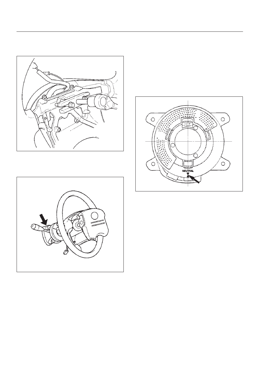
1. Install combination switch and SRS coil assembly.

After installation of combination switch assembly,
connect the combination switch wiring harness
connector and the SRS 2-way connector located
under the steering column.  Then turn the SRS coil
counter clockwise to full, return about 3 turns and
align the neutral mark.

CAUTION: Turn the SRS coil counter clockwise
until some resistance is felt, or damage may occur to
the SRS coil.

825RW016

POWER–ASSISTED STEERING SYSTEM

2A–39

2. When installing the steering column cover, be sure to

route each wire harness as illustrated so that the
harnesses do not catch on any moving parts.

825RW017

Legend

(1) Steering Column Cover
(2) Starter Switch Harness
(3) Combination Switch Harness
(4) Inflator Module Harness

3. Align the setting marks made when removing then

install steering wheel.

CAUTION: Never apply force to the steering wheel
shaft using a hammer or other impact tools in an
attempt to remove the steering wheel.  The steering
shaft is designed as an energy absorbing unit.

4. Tighten the steering wheel fixing nut to the specified

torque.

Torque: 34 N·m (25 lb ft)

5. Support the inflator module and carefully connect the

SRS connector and horn lead.

NOTE: Pass the lead wire through the tabs on the plastic
cover (wire protector) of inflator to prevent lead wire from
being pinched.

6. Tighten bolts to specified torque.

Torque: 9 N·m (78 lb in)

7. Install driver knee bolster (reinforcement).
8. Install instrument panel lower cover then Install the

engine hood opening lever.

9. Connect  the SRS connector.

10. Connect the battery “-” terminal cable.

11. Turn the ignition switch to the “ON” position and

observe the warning lamp. The lamp should flash 7
times. If the lamp does not operate correctly, refer to
Restraints section.

2A–40 POWER–ASSISTED STEERING SYSTEM

Lock Cylinder

Lock Cylinder and Associated Parts

431RX005

Legend

(1) Inflator Module
(2) Steering Wheel
(3) Steering Column Cover
(4) Combination Switch and SRS Coil Assembly
(5) Snap Ring

(6) Cushion Rubber
(7) Lock Cylinder Assembly
(8) Instrument Panel Lower Cover
(9) Driver Knee Bolster (reinforcement)

(10) Shift Lock Cable (for A/T)

Removal

1. Turn the steering wheel so that the vehicle’s wheels

are pointing straight ahead.

2. Turn the ignition switch to “LOCK”.
3. Disconnect the battery ground cable, and wait at least

5 minutes.

4. Disconnect the yellow 2-way SRS connector located

under the steering column.

CAUTION: The wheels of the vehicle must be
straight ahead and the steering column in the
”LOCK” position before disconnecting the steering
wheel.  Failure to do so will cause the coil assembly
to become uncentered which will cause damage to
the coil assembly.

5. Remove the engine hood opening lever and steering

lower cover.

6. Remove driver knee bolster (reinforcement).

POWER–ASSISTED STEERING SYSTEM

2A–41

7. Loosen the inflator module fixing bolt from behind the

steering wheel assembly using a TORX

 driver or

equivalent until the inflator module can be released
from steering assembly.

827RW070

8. Disconnect the yellow 2-way SRS connector and

horn lead located behind the inflator module.

827RW073

9. Apply a setting mark (1) across the steering wheel

and shaft so parts can be reassembled in their original
position.

430RW021

10. Move the front wheels to the straight ahead position,

then use steering wheel remover  J–29752 to remove
the steering wheel. 

CAUTION: Never apply force to the steering wheel
shaft using a hammer or other impact tools in an
attempt to remove the steering wheel. The steering
shaft is designed as an energy absorbing unit.

430RX005


Content   ..  46  47  48  49   ..