Isuzu KB P190. Manual - part 214


  Index      Isuzu     Isuzu KB P190 - service repair manual 2007 year


Search            


Content   ..  212  213  214  215   ..


Isuzu KB P190. Manual - part 214


ENGINE MECHANICAL   6A – 51 


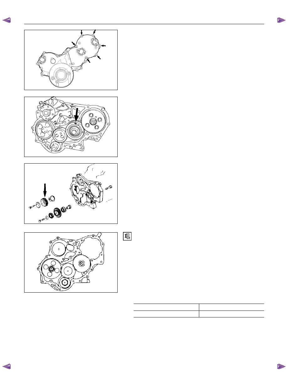
10. Timing Gear Case Cover 

The timing gear case is tightened together with the 
injection pump at the 6 points indicated by the arrows in 
the illustration. 


11. Water Pump 


12. Idle Gear B and shaft 

Before removing the idle gear B, install bolt (M6,L=30) to 
the hole marked with an arrow in the illustration to hold the 
scissor gear in place. 


13. Idler Gear "A" 

1.  Measure the camshaft timing gear backlash and the 

crankshaft timing gear backlash before removing the 
idler gear. 

2.  Measure the idler gear end play before removing the 

idler gear. 


NOTE: 

Refer to the following items for details on the backlash 
and end play measurement procedures. 


Timing Gear Backlash Measurement 

1.  Set a dial indicator to the timing gear to measured. 

Hold both the gear to be checked and the adjusting 
gear stationary. 

2.  Move the gear to be checked as far as possible to 

both the right and the left. 
Take the dial indicator reading. 
If the measured value exceeds the specified limit, the 
timing gear must be replaced. 


Timing Gear Backlash 

mm (in)

Standard Limit 

0.10 - 0.17 (0.0039 - 0.0067)

0.30 (0.012) 


020L200006

020L200020

020RY00019

020RY00020

6A – 52  ENGINE MECHANICAL 


RTW36ASH000801 

Idler Gear "A" End Play Measurement 

Insert a feeler gauge between the idler gear and the thrust 
collar to measure the gap and determine the idler gear 
end play. 

If the measured value exceeds the specified limit, the 
thrust collar must be replaced. 


Idler Gear End Play 

mm (in)

Standard Limit 

0.07 (0.0028) 

0.2 (0.0079) 


4JA1T(L)

040R300009 


14. Idle Gear Shaft 

15. Crankshaft Timing Gear 


4JA1TC/4JH1TC 

RTW36ASH001301 


16. Injection Pump 

1.  Remove the injection pump cover (4JA1TC/4JH1TC 

only). 

2.  Remove the injection pump bracket. 

3.  Pull the injection pump along with the injection pump 

timing gear free toward the rear of the engine. 


NOTE: 

Plug the injection pump delivery ports with the caps to 
prevent the entry of foreign material.


17. Flywheel 

Loosen the flywheel bolts in numerical order a little at a 
time. 
Use the gear stoper to stop the flywheel gear. 
Gear stoper: 5-8840-0214-0 


18. Crank Case 


19. Oil Pump With Oil Pipe 


015RY00001

ENGINE MECHANICAL   6A – 53 


20. Camshaft Timing Gear 

1.  Use a dial indicator to measure the camshaft end play.

This must be done before removing the camshaft 
gear. 
If the camshaft end play exceeds the specified limit, 
the thrust plate must be replaced. 


Camshaft End Play 

mm (in)

Standard Limit 

0.050 - 0.114 

(0.002 - 0.0044) 

0.20 

(0.008) 


2.  Remove the camshaft timing gear bolt from the 

camshaft. 

Note: 

Hold the camshaft stationary to prevent the camshaft 
from turning. 

3.  Remove the sensor rotor plate. 

4.  Use the universal puller to pull out the camshaft  

timing gear. 
Universal Puller: 5-8521-0002-0 

5.  Remove the thrust plate. 


21. Camshaft Thrust Plate 


22. Camshaft 

Jiggle the camshaft with your hand as you pull it free from 
the front of the engine. 


23. Timing Gear Case 


24. Cylinder Body Rear Plate 


25. Piston Cooling Oil Jet 

The oiling jet uses thin steel tubing which is easily bent. 

Accidental contact between the oiling jet and the cylinder 
body, piston, or a tool will damage the oiling jet. 

Never attempt to repair a damaged oiling jet. Replace it 
with a new one. 


014RT0001

901R100008

014RY00019

052RY00001

6A – 54  ENGINE MECHANICAL 


26. Connecting Rod Bearing Cap with Lower Bearing 

If the connecting rod lower bearings are to be reinstalled, 
mark their fitting positions by tagging each bearing with the 
cylinder number from which it was removed. 


27. Piston and Connecting Rod with Upper Bearing 

1.  Remove carbon deposits from the upper portion of the 

cylinder wall with a scraper before removing the piston 
and connecting rod. 

2.  Move the piston to the top of the cylinder and tap it 

with a hammer grip or a similar object from the 
connecting rod lower side to drive it out. 


RTW36ASH001501 


If the connecting rod upper bearings are to be reinstalled, 
mark their fitting positions by tagging each bearing with the 
cylinder number from which it was removed. 


28. Crankshaft Bearing Cap with Lower Bearing 

1.  Measure the crankshaft end play at the center journal 

of the crankshaft. 
Do this before removing the crankshaft bearing caps. 
If the measured value exceeds the specified limit, the 
crankshaft thrust bearing must be replaced. 


Crankshaft End Play 

mm (in)

Standard Limit 

0.10 (0.004) 

0.30 (0.012) 


014LX056

015LX018

015RY00002


Content   ..  212  213  214  215   ..