Content .. 1141 1142 1143 1144 ..
Isuzu KB P190. Manual - part 1143
7B-8 MSG MODEL
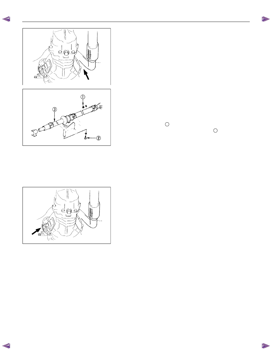
Exhaust Pipe
1. Remove the exhaust pipe bracket from the transmission
case.
2. Remove the exhaust pipe.
Rear Propeller Shaft (Dual Shaft Type)
1. Apply setting marks to the 2nd propeller shaft flange yoke.
This will prevent mispositioning during the installation
procedure.
2. Remove the 2nd propeller shaft flange yoke nuts at the
drive pinion side
1
.
3. Remove the center bearing retainer bolts
2
.
4. Remove the 1st propeller shaft with the center bearing and
the 2nd propeller shaft.
Pull the 1st propeller shaft toward the rear of the vehicle
until the spline yoke is free of the transmission main shaft.
Harness Connector
Disconnect the back up light switch connector and the
speedometer sensor connector.
Slave Cylinder
Remove the slave cylinder from the transmission case.