Infiniti QX4 (R50). Manual - part 551


  Index      Infiniti     Infiniti QX4 (R50) - service repair manual 2001 year


Search            copyright infringement  


Content   ..  549  550  551  552   ..


Infiniti QX4 (R50). Manual - part 551


SST051C

3.

Remove tie-rod outer sockets and boots.

4.

Loosen tie-rod inner socket by prying up staked portion, and
remove socket.

5.

Remove retainer.

6.

Remove pinion assembly.

7.

Use a 2 to 2.5 mm (0.079 to 0.098 in) diameter drill to com-
pletely remove staked portion of gear housing end.

SST652C

8.

Remove gear housing end cover assembly with a suitable tool.

9.

Draw out rack assembly.

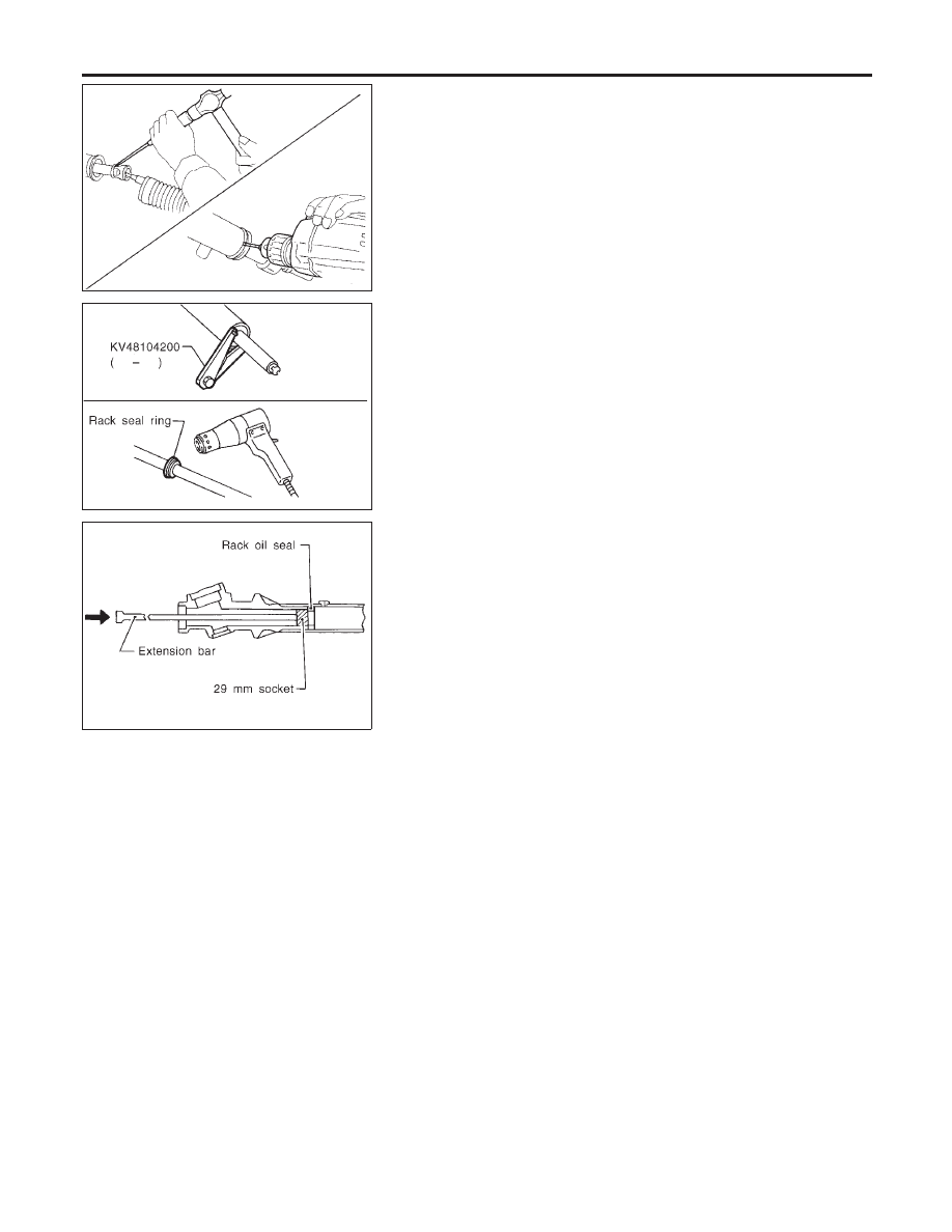
10. Remove rack seal ring.

I

Using a heat gun, heat rack seal to approximately 40°C
(104°F).

I

Remove rack seal ring.

Be careful not to damage rack.

SST644C

11. Remove rack bushing and rack oil seal using tape wrapped

socket and extension bar.

Do not scratch inner surfaces of pinion housing.

Inspection

NBST0029

Thoroughly clean all parts in cleaning solvent or Genuine Nissan
PSF II or equivalent. Blow dry with compressed air, if available.

BOOT

NBST0029S01

I

Check condition of boot. If cracked excessively, replace it.

I

Check boots for accumulation of power steering fluid.

RACK

NBST0029S02

Thoroughly examine rack gear. If damaged, cracked and worn,
replace it.

PINION ASSEMBLY

NBST0029S03

I

Thoroughly examine pinion gear. If pinion gear is damaged,
cracked and worn, replace it.

I

Check that all bearings roll freely. Ensure that balls, rollers and
races are not cracked, pitted and worn.

GEAR HOUSING CYLINDER

NBST0029S04

Check gear housing cylinder bore for scratches and other damage.
Replace if necessary.

POWER STEERING GEAR AND LINKAGE

Disassembly (Cont’d)

ST-20

SST468C

TIE-ROD OUTER AND INNER SOCKETS

NBST0029S05

I

Check ball joints for swinging force.

Tie-rod outer and inner ball joints swinging force “A”:

Refer to SDS, ST-33.

I

Check ball joint for rotating torque.

Tie-rod outer ball joint rotating torque “B”:

Refer to SDS, ST-33.

I

Check ball joints for axial end play.

Tie-rod outer and inner ball joints axial end play “C”:

Refer to SDS, ST-33.

I

Check condition of dust cover. If cracked excessively, replace
outer tie-rod.

SST083B

Assembly

NBST0030

1.

Using a heat gun, heat new teflon rack seal ring to approxi-
mately 40°C (104°F). Then place it onto rack.

SBR132C

2.

Using Tool, compress rack seal ring securely on rack.

Always insert Tool from the rack gear side.

SST201A

3.

Insert new rack oil seal.

I

Place plastic film into rack oil seal to prevent damage by
rack teeth.

I

Do not forget to remove plastic film after rack oil seal is
positioned properly.

I

Make sure lips of rack oil seal face each other.

GI

MA

EM

LC

EC

FE

AT

TF

PD

AX

SU

BR

RS

BT

HA

SC

EL

IDX

POWER STEERING GEAR AND LINKAGE

Inspection (Cont’d)

ST-21

SST645C

4.

Install rack oil seal and rack bushing with rack assembly.

SST653C

5.

Insert rack oil seal and end cover assembly to rack. Then
tighten end cover assembly.

SST654C

6.

Fasten cylinder end cover assembly to gear housing by stak-
ing.

SST651C

7.

Set rack gear in the neutral position.

Rack stroke “S”:

Refer to SDS, ST-33.

SST381A

8.

Coat seal lip of new pinion oil seal with multi-purpose grease.
Install it into pinion housing of gear with a suitable tool.

Make sure lip of oil seal faces up when installed.

POWER STEERING GEAR AND LINKAGE

Assembly (Cont’d)

ST-22

SST074B

9.

Install pinion bearing adjusting shim(s).

I

Whenever pinion assembly, gear housing and rear housing are
disassembled, replace shim(s) with new ones. Always use the
same number of shim(s) when replacing.

SST085B

10. Install new pinion seal ring (made of Teflon) on pinion gear

assembly.

I

Using a heat gun, heat pinion seal ring to approximately 40°C
(104°F) before installing it onto pinion gear assembly.

I

Make sure pinion seal ring is properly settled in valve groove.

SST075B

11. Apply a coat of multi-purpose grease to needle bearing roller

and oil seal lip.

SST552

12. Install pinion assembly to rear housing.
Be careful not to damage pinion oil seal.

SST133C

13. Apply a coat of multi-purpose grease to new rear oil seal lip

before installing rear housing.

GI

MA

EM

LC

EC

FE

AT

TF

PD

AX

SU

BR

RS

BT

HA

SC

EL

IDX

POWER STEERING GEAR AND LINKAGE

Assembly (Cont’d)

ST-23


Content   ..  549  550  551  552   ..