Infiniti QX4 (R50). Manual - part 550


  Index      Infiniti     Infiniti QX4 (R50) - service repair manual 2001 year


Search            copyright infringement  


Content   ..  548  549  550  551   ..


Infiniti QX4 (R50). Manual - part 550


SST847C

Installation

NBST0022

1.

Set wheels in the straight-ahead position.

2.

Install transfer gear assembly.

3.

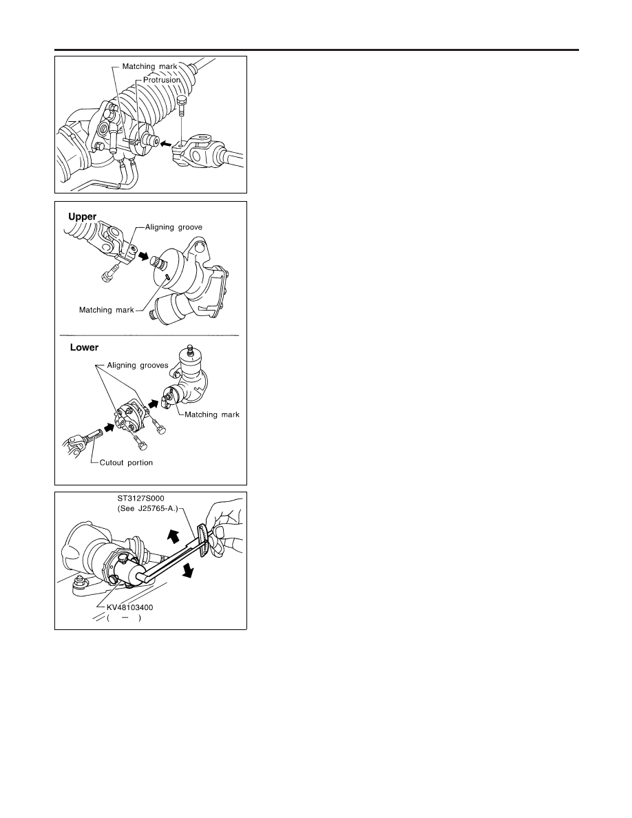
Install column lower joint while aligning groove with protrusions
on the steering gear rear cover cap.

4.

Tighten bolt while aligning groove on steering gear. Before
tightening bolt, ensure it is inserted correctly.

SST848C

5.

When attaching steering column upper and lower joint to trans-
fer gear, it must be positioned as shown in figure at left.

SST707CA

Inspection

NBST0024

Do not disassemble steering transfer gear assembly.

I

Check that steering transfer gear assembly operates smoothly.
Also check for grease leakage, deformation and damage.
Replace steering transfer gear assembly if necessary.

I

Check rotating torque at input shaft in 360° and in both direc-
tions.

Rotating torque:

0.25 - 0.69 N·m (2.5 - 7.0 kg-cm, 2.2 - 6.1 in-lb)

If rotating torque is out of specification, replace steering trans-
fer gear assembly.

STEERING TRANSFER GEAR

Installation

ST-16

Components

NBST0026

SST618CB

1.

Rear cover cap

2.

Rear housing assembly

3.

Pinion seal ring

4.

Pinion assembly

5.

O-ring

6.

Shim

7.

Pinion oil seal

8.

Lock nut

9.

Adjusting screw

10. Spring

11. Retainer
12. Gear housing assembly
13. Rack oil seal
14. Rack assembly
15. Rack seal ring
16. O-ring
17. O-ring
18. Rack bushing
19. Rack oil seal
20. Snap ring

21. End cover assembly
22. Boot clamp
23. Dust boot
24. Boot clamp
25. Lock plate
26. Tie-rod inner socket
27. Tie-rod
28. Tie-rod outer socket
29. Cotter pin
30. Cylinder tube

GI

MA

EM

LC

EC

FE

AT

TF

PD

AX

SU

BR

RS

BT

HA

SC

EL

IDX

POWER STEERING GEAR AND LINKAGE

Components

ST-17

Removal and Installation

NBST0027

SST614C

1.

Gear and linkage assembly

2.

Rack mounting insulator

3.

Gear housing mounting bracket

4.

Cotter pin

SFA756B

CAUTION:

I

The rotation of the spiral cable (SRS “AIR BAG” compo-
nent part) is limited. If the steering gear must be removed,
set the front wheels in the straight-ahead direction. Do not
rotate the steering column while the steering gear is
removed.

I

Remove the steering wheel before removing the steering
lower joint to avoid damaging the SRS spiral cable.

I

Detach tie-rod outer sockets from knuckle arms with Tool.

SST615C

I

Install pipe connector.

I

Observe specified tightening torque when tightening high-pres-
sure and low-pressure pipe connectors. Excessive tightening
will damage threads of connector or O-ring.

Connector tightening torque:

Low-pressure side “1”

30 - 35 N·m (3.1 - 3.6 kg-m, 22 - 26 ft-lb)

High-pressure side “2”

30 - 35 N·m (3.1 - 3.6 kg-m, 22 - 26 ft-lb)

I

The O-ring in low-pressure pipe connector is larger than that

POWER STEERING GEAR AND LINKAGE

Removal and Installation

ST-18

in high-pressure connector. Take care to install the proper
O-ring.

SST616C

I

Initially, tighten nut on tie-rod outer socket and knuckle arm to
64 to 69 N·m (6.5 to 7.0 kg-m, 47 to 51 ft-lb). Then tighten fur-
ther to align nut groove with first pin hole so that cotter pin can
be installed.

CAUTION:

Tightening torque must not exceed 108 N·m (11.0 kg-m, 80 ft-
lb).

SST819A

I

Before removing steering column lower joint from gear, set
gear in neutral (wheels in straight-ahead position). After
removing steering column lower joint, put matching mark on
pinion shaft and pinion housing to record neutral position.

I

To install, set left and right dust boots to equal deflection.
Attach steering column lower joint by aligning matching marks
of pinion shaft and pinion housing.

SST617C

I

Tighten gear housing mounting bracket bolts in the order
shown.

Secure tightening torque:

118 - 137 N·m (12 - 14 kg-m, 87 - 101 ft-lb)

SST718CA

Disassembly

NBST0028

1.

Prior to disassembling, measure pinion rotating torque. Record
the pinion rotating torque as a reference.

I

Before measuring, disconnect cylinder tube and drain
fluid.

I

Use soft jaws when holding steering gear housing. Handle
gear housing carefully, as it is made of aluminum. Do not
grip cylinder in a vise.

2.

Remove pinion gear.

Be careful not to damage pinion gear when removing pinion
seal ring.

GI

MA

EM

LC

EC

FE

AT

TF

PD

AX

SU

BR

RS

BT

HA

SC

EL

IDX

POWER STEERING GEAR AND LINKAGE

Removal and Installation (Cont’d)

ST-19


Content   ..  548  549  550  551   ..