Infiniti QX4 (R50). Manual - part 549
SRS266
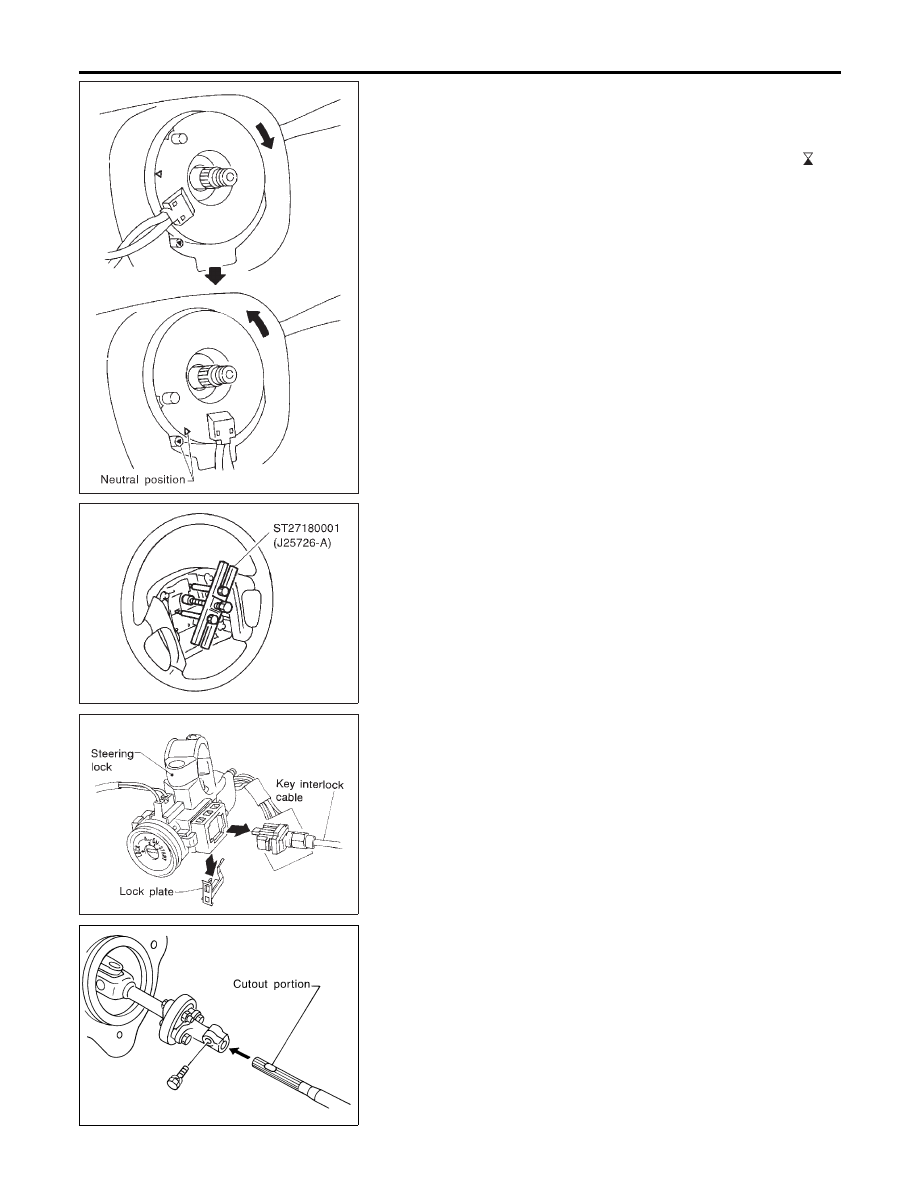
2.
Align spiral cable correctly when installing steering wheel.
a.
Set the front wheels in the straight-ahead position.
b.
Make sure that the spiral cable is in the neutral position.
The neutral position is detected by turning left about 2.5 revo-
lutions from the right end position. Align the two marks (
).
CAUTION:
I
The spiral cable may snap due to steering operation if the
cable is installed in an improper position.
I
Also, with the steering linkage disconnected, the cable
may snap by turning the steering wheel beyond the limited
number of turns. The spiral cable can be turned to the left
about 2.5 turns from the right end position.
SST818C
3.
Remove steering wheel with Tool.
SST329C
4.
Remove key interlock cable.
SST844C
STEERING COLUMN
NBST0017S02
I
When installing steering column, fingertighten all lower bracket
and clamp retaining bolts; then tighten them securely. Do not
apply undue stress to steering column.
I
When attaching coupling joint, be sure tightening bolt faces
cutout portion.
STEERING WHEEL AND STEERING COLUMN
Removal and Installation (Cont’d)
ST-12