Infiniti QX4 (R50). Manual - part 534


  Index      Infiniti     Infiniti QX4 (R50) - service repair manual 2001 year


Search            copyright infringement  


Content   ..  532  533  534  535   ..


Infiniti QX4 (R50). Manual - part 534


SRS702

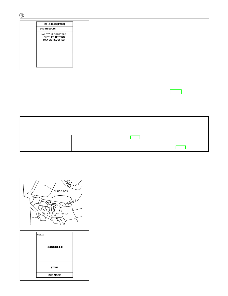
10. Check that no malfunction is detected on “SELF-DIAG

[PAST]”.

11. Touch “BACK” key of CONSULT-II until “SELECT SYSTEM”

appears in order to return to User mode from Diagnosis mode.

12. Turn ignition switch “OFF”, then turn off and disconnect CON-

SULT-II.

13. Go to “SRS Operation Check”, page RS-38 to check SRS

operation by using “AIR BAG” warning lamp with User mode.

DIAGNOSTIC PROCEDURE 4 (CONTINUED FROM
DIAGNOSTIC PROCEDURE 2)

NBRS0045S03

Inspecting SRS malfunctioning record

1

CONSIDER POSSIBILITY OF NOT ERASING SELF-DIAGNOSTIC RESULT AFTER REPAIRING

Is it the first time for maintenance of SRS?

Yes or No

Yes

©

Go to DIAGNOSTIC PROCEDURE 5 (RS-44).

No

©

Self-diagnostic result “SELF-DIAG [PAST]” (previously stored in the memory) might not
be erased after repair. Go to DIAGNOSTIC PROCEDURE 3, step 8 (RS-42).

SRS844

DIAGNOSTIC PROCEDURE 5

NBRS0045S04

Inspecting SRS intermittent malfunction by using CONSULT-II
— Diagnosis mode
1.

Turn ignition switch “OFF”.

2.

Connect CONSULT-II to Data link connector.

SRS695

3.

Turn ignition switch “ON”.

4.

Touch “START”.

SUPPLEMENTAL RESTRAINT SYSTEM (SRS)

Trouble Diagnoses with CONSULT-II (Cont’d)

RS-44

SRS771

5.

Touch “AIR BAG”.

SRS697

6.

Touch “SELF-DIAG [PAST]”.

SRS700

7.

If diagnostic codes are displayed on “SELF-DIAG [PAST]”, go
to step 10.

SRS702

If no malfunction is detected on “SELF-DIAG [PAST]”, touch
“BACK” and go back to “SELECT DIAG MODE”.

SRS697

8.

Touch “TROUBLE DIAG RECORD”.

NOTE:
With “TROUBLE DIAG RECORD”, diagnosis results previ-
ously erased by a reset operation can be displayed.

GI

MA

EM

LC

EC

FE

AT

TF

PD

AX

SU

BR

ST

BT

HA

SC

EL

IDX

SUPPLEMENTAL RESTRAINT SYSTEM (SRS)

Trouble Diagnoses with CONSULT-II (Cont’d)

RS-45

SRS704

9.

Diagnostic code is displayed on “TROUBLE DIAG RECORD”.

10. Touch “PRINT”.
11. Compare diagnostic codes to “Intermittent Malfunction Diag-

nostic Code Chart”, page RS-46.

12. Touch “BACK” key of CONSULT-II until “SELECT SYSTEM”

appears.

13. Turn ignition switch “OFF”, then turn off and disconnect

CONSULT-II, and disconnect both battery cables.

14. Repair the system as outlined by the “Repair order” in “Inter-

mittent Malfunction Diagnostic Code Chart”, that corresponds
to the self-diagnostic result. For replacement procedure of
component parts, refer to RS-15.

15. Go to DIAGNOSTIC PROCEDURE 3, page RS-42, for final

checking.

Intermittent Malfunction Diagnostic Code Chart (“SELF-
DIAG [PAST]” or “TROUBLE DIAG RECORD”)

NBRS0045S0401

Diagnostic item

Explanation

Repair order

NO DTC IS
DETECTED.

When malfunction is
indicated by the “AIR
BAG” warning lamp in
User mode

I

Low battery voltage (Less than 9V)

I

Go to DIAGNOSTIC PROCEDURE
(RS-42) after charging battery.

I

No malfunction is detected.

I

Go to DIAGNOSTIC PROCEDURE
(RS-42).

AIRBAG MODULE
[OPEN]

I

Driver’s air bag module circuit is open. (including the spiral
cable)

1. Visually check the wiring harness

connection.

2. Replace the harness if it has visible

damage.

3. If the harness check result is OK,

replace driver’s air bag module
(Before disposal of it, it must be
deployed.), diagnosis sensor unit
and spiral cable.

AIRBAG MODULE
[VB-SHORT]

I

Driver’s air bag module circuit is shorted to some power sup-
ply circuit. (including the spiral cable)

AIRBAG MODULE
[GND-SHORT]

I

Driver’s air bag module circuit is shorted to ground. (including
the spiral cable)

AIRBAG MODULE
[SHORT]

I

Driver’s air bag module circuits are shorted to each other.

ASSIST A/B MODULE
[VB-SHORT]

I

Front passenger air bag module circuit is shorted to some
power supply circuit.

1. Visually check the wiring harness

connection.

2. Replace the harness if it has visible

damage.

3. If the harness check result is OK,

replace front air bag module
(Before disposal of it, it must be
deployed.), and diagnosis sensor
unit.

ASSIST A/B MODULE
[OPEN]

I

Front passenger air bag module circuit is open.

ASSIST A/B MODULE
[GND-SHORT]

I

Front passenger air bag module circuit is shorted to ground.

ASSIST A/B MODULE
[SHORT]

I

Front passenger air bag module circuits are shorted to each
other.

SUPPLEMENTAL RESTRAINT SYSTEM (SRS)

Trouble Diagnoses with CONSULT-II (Cont’d)

RS-46

Diagnostic item

Explanation

Repair order

SIDE MODULE LH
[OPEN]

I

Side air bag module (LH) circuit is open.

1. Visually check the wiring harness

connection.

2. Replace the harness if it has visible

damage.

3. If the harness check is OK, replace

the diagnosis sensor unit and side
air bag module (LH). (Before dis-
posing the side air bag module
(LH), it must be deployed.)

SIDE MODULE LH
[VB-SHORT]

I

Side air bag module (LH) circuit is shorted to some power
supply circuits.

SIDE MODULE LH
[GND-SHORT]

I

Side air bag module (LH) circuit is shorted to ground.

SIDE MODULE LH
[SHORT]

I

Side air bag module (LH) circuits are shorted to each other.

SIDE MODULE RH
[OPEN]

I

Side air bag module (RH) circuit is open.

1. Visually check the wiring harness

connection.

2. Replace the harness if it has visible

damage.

3. If the harness check is OK, replace

the diagnosis sensor unit and side
air bag module (RH). (Before dis-
posing the side air bag module
(RH), it must be deployed.)

SIDE MODULE RH
[VB-SHORT]

I

Side air bag module (RH) circuit is shorted to some power
supply circuits.

SIDE MODULE RH
[GND-SHORT]

I

Side air bag module (RH) circuit is shorted to ground.

SIDE MODULE RH
[SHORT]

I

Side air bag module (RH) circuits are shorted to each other.

SATELLITE SENS LH
[UNIT FAIL]
SATELLITE SENS LH
[COMM FAIL]

I

Satellite sensor (LH)

1. Visually check the wiring harness

connection.

2. Replace the harness if it has visible

damage.

3. If the harness check is OK, replace

the diagnosis sensor unit and satel-
lite sensor (LH).

SATELLITE SENS RH
[UNIT FAIL]
SATELLITE SENS RH
[COMM FAIL]

I

Satellite sensor (RH)

1. Visually check the wiring harness

connection.

2. Replace the harness if it has visible

damage.

3. If the harness check is OK, replace

the diagnosis sensor unit and satel-
lite sensor (RH).

PRE-TEN FRONT LH
[OPEN/VB-SHORT]

I

The circuit for front LH pre-tensioner is open or shorted to
some power supply circuit.

1. Visually check the wiring harness

connections.

2. Replace the harness if it has visible

damage.

3. If the harness check is OK, replace

the diagnosis sensor unit and front
LH seat belt.
(Before disposing the front LH seat
belt pre-tensioner, it must be
deployed.)

PRE-TEN FRONT LH
[GND-SHORT]

I

The circuit for front LH pre-tensioner is shorted to ground.

PRE-TEN FRONT RH
[OPEN/VB-SHORT]

I

The circuit for front RH pre-tensioner is open or shorted to
some power supply circuit.

1. Visually check the wiring harness

connections.

2. Replace the harness if it has visible

damage.

3. If the harness check is OK, replace

the diagnosis sensor unit and front
RH seat belt.
(Before disposing the front RH seat
belt pre-tensioner, it must be
deployed.)

PRE-TEN FRONT RH
[GND-SHORT]

I

The circuit for front RH pre-tensioner is shorted to ground.

GI

MA

EM

LC

EC

FE

AT

TF

PD

AX

SU

BR

ST

BT

HA

SC

EL

IDX

SUPPLEMENTAL RESTRAINT SYSTEM (SRS)

Trouble Diagnoses with CONSULT-II (Cont’d)

RS-47


Content   ..  532  533  534  535   ..