Infiniti QX4 (R50). Manual - part 455


  Index      Infiniti     Infiniti QX4 (R50) - service repair manual 2001 year


Search            copyright infringement  


Content   ..  453  454  455  456   ..


Infiniti QX4 (R50). Manual - part 455


3. Capacity Control

=NBHA0087S0203

I

Refrigerant pressure on suction side is low during high speed driving or when ambient or interior tempera-
ture is low.

I

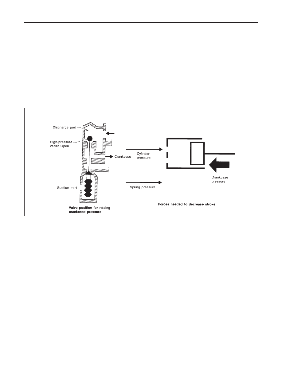
The bellows expands when refrigerant pressure on the suction pressure side drops below approximately
177 kPa (1.8 kg/cm

2

, 26 psi).

Since suction pressure is low, it makes the suction port close and the discharge port open. Thus, crank-
case pressure becomes high as high pressure enters the crankcase.

I

The force acts around the journal pin near the swash plate, and is generated by the pressure difference
before and behind the piston.
The drive lug and journal pin are located where the piston generates the highest pressure. Piston pres-
sure is between suction pressure Ps and discharge pressure Pd, which is near suction pressure Ps. If
crankcase pressure Pc rises due to capacity control, the force around the journal pin makes the swash
plate angle decrease and also the piston stroke decrease. In other words, crankcase pressure increase
triggers pressure difference between the piston and the crankcase. The pressure difference changes the
angle of the swash plate.

RHA474C

DESCRIPTION

V-6 Variable Displacement Compressor (Cont’d)

HA-18

Component Layout

NBHA0012

RHA451G

GI

MA

EM

LC

EC

FE

AT

TF

PD

AX

SU

BR

ST

RS

BT

SC

EL

IDX

DESCRIPTION

Component Layout

HA-19

Introduction

NBHA0013

AIR CONDITIONER LAN SYSTEM OVERVIEW CONTROL SYSTEM

NBHA0013S01

The LAN system consists of auto amp., air mix door motor and mode door motor.
A configuration of these components is shown in the diagram below.

RHA439G

Features

NBHA0014

SYSTEM CONSTRUCTION (LAN)

NBHA0014S08

A small network is constructed between the auto amplifier, air mix door motor and mode door motor. The auto
amplifier and motors are connected by data transmission lines and motor power supply lines. The LAN net-
work is built through the ground circuits of the two motors.
Addresses, motor opening angle signals, motor stop signals and error checking messages are all transmitted
through the data transmission lines connecting the auto amplifier and two motors.
The following functions are contained in LCUs built into the air mix door motor and the mode door motor.

I

Address

I

Motor opening angle signals

I

Data transmission

I

Motor stop and drive decision

I

Opening angle sensor (PBR function)

I

Comparison

I

Decision (Auto amplifier indicated value and motor opening angle comparison)

RHA440GA

Operation

NBHA0014S0801

The auto amplifier receives data from each of the sensors. The amplifier sends air mix door and mode door
opening angle data to the air mix door motor LCU and mode door motor LCU.
The air mix door motor and mode door motor read their respective signals according to the address signal.
Opening angle indication signals received from the auto amplifier and each of the motor position sensors are
compared by the LCUs in each motor with the existing decision and opening angles. Subsequently, HOT/
COLD or DEFROST/VENT operation is selected. The new selection data is returned to the auto amplifier.

DESCRIPTION

Introduction

HA-20

RHA441GA

Transmission Data and Transmission Order

NBHA0014S0802

Amplifier data is transmitted consecutively to each of the door motors following the form shown in figure below.
Start: Initial compulsory signal sent to each of the door motors.
Address: Data sent from the auto amplifier is selected according to data-based decisions made by the air mix
door motor and mode door motor.
If the addresses are identical, the opening angle data and error check signals are received by the door motor
LCUs. The LCUs then make the appropriate error decision. If the opening angle data is normal, door control
begins.
If an error exists, the received data is rejected and corrected data received. Finally, door control is based upon
the corrected opening angle data.
Opening angle: Data that shows the indicated door opening angle of each door motor.
Error check: Procedure by which sent and received data is checked for errors. Error data is then compiled.
The error check prevents corrupted data from being used by the air mix door motor and mode door motor.
Error data can be related to the following problems.

I

Abnormal electrical frequency

I

Poor electrical connections

I

Signal leakage from transmission lines

I

Signal level fluctuation

Stop signal: At the end of each transmission, a stop operation, in-operation, or internal problem message is
delivered to the auto amplifier. This completes one data transmission and control cycle.

RHA442G

Air Mix Door Control (Automatic Temperature Control)

NBHA0014S0803

The air mix door is automatically controlled so that in-vehicle temperature is maintained at a predetermined
value by: The temperature setting, ambient temperature, in-vehicle temperature and amount of sunload.

GI

MA

EM

LC

EC

FE

AT

TF

PD

AX

SU

BR

ST

RS

BT

SC

EL

IDX

DESCRIPTION

Features (Cont’d)

HA-21


Content   ..  453  454  455  456   ..