Infiniti QX4 (R50). Manual - part 454
Refrigeration System
REFRIGERATION CYCLE
NBHA0010
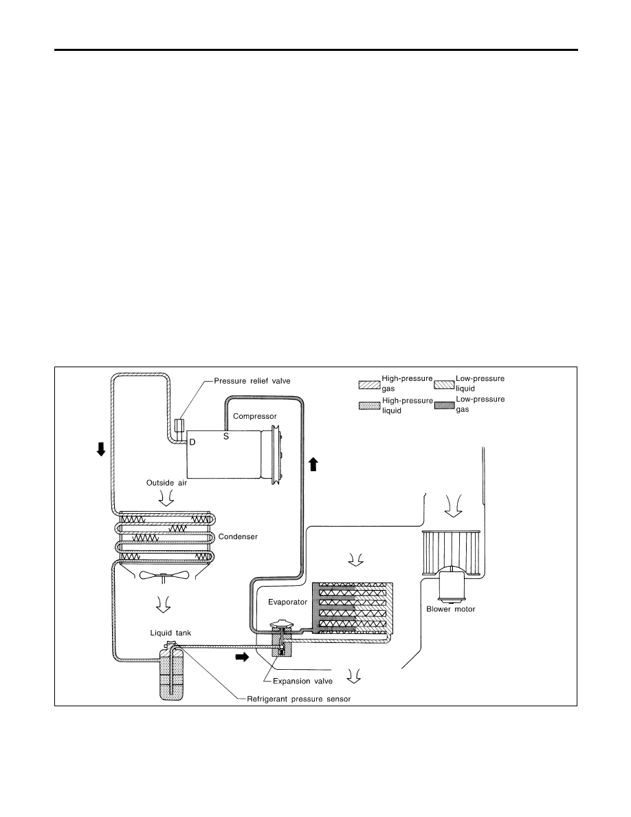
Refrigerant Flow
NBHA0010S01
The refrigerant flows in the standard pattern, that is, through the compressor, the condenser, the liquid tank,
through the evaporator, and back to the compressor. The refrigerant evaporation through the evaporator coil
is controlled by an externally equalized expansion valve, located inside the evaporator case.
Freeze Protection
NBHA0010S02
Under normal operating conditions, when the A/C is switched on, the compressor runs continuously, and the
evaporator pressure, and therefore temperature, is controlled by the V-6 variable displacement compressor to
prevent freeze up.
Refrigerant System Protection
NBHA0010S03
Refrigerant Pressure Sensor
NBHA0010S0303
The refrigerant system is protected against excessively high or low pressures by the refrigerant pressure
sensor, located on the liquid tank. If the system pressure rises above, or falls below the specifications, the
refrigerant pressure sensor detects the pressure inside the refrigerant line and sends the voltage signal to the
ECM. ECM makes the A/C relay go OFF and stops the compressor when pressure on the high pressure side
detected by refrigerant pressure sensor is over about 2,746 kPa (28 kg/cm
2
, 398 psi) or below about 177 kPa
(1.8 kg/cm
2
, 26 psi).
Pressure Relief Valve
NBHA0010S0302
The refrigerant system is also protected by a pressure relief valve, located in the rear head of the compres-
sor. When the pressure of refrigerant in the system increases to an abnormal level [more than 3,727 kPa (38
kg/cm
2
, 540 psi)], the release port on the pressure relief valve automatically opens and releases refrigerant
into the atmosphere.
RHA347H
DESCRIPTION
Refrigeration System
HA-14