Infiniti QX4 (R50). Manual - part 418
SEM426G
7.
After confirming the mating marks are aligned, tighten the cam-
shaft sprocket mounting bolts.
I
Secure the camshaft hexagonal head using a spanner to
tighten mounting bolts.
SEM425G
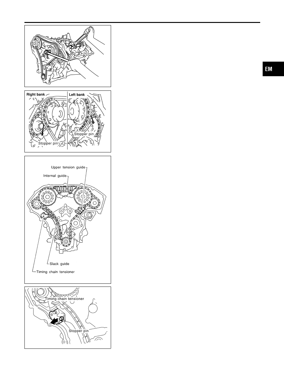
8.
Pull out the stopper pin from the secondary timing chain ten-
sioner.
SEM919EA
9.
Install internal guide.
10. Install upper tension guide and slack guide.
SEM967F
11. Install timing chain tensioner, then remove the stopper pin.
I
When installing the timing chain tensioner, engine oil
should be applied to the oil hole and tensioner.
GI
MA
LC
EC
FE
AT
TF
PD
AX
SU
BR
ST
RS
BT
HA
SC
EL
IDX
TIMING CHAIN
Installation (Cont’d)
EM-31