Infiniti QX4 (R50). Manual - part 321
Trouble Diagnoses
NBEL0201
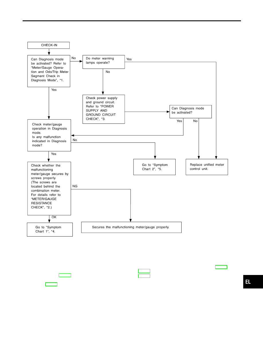
PRELIMINARY CHECK
NBEL0201S01
SEL361W
*1: Meter/Gauge Operation and Odo/
Trip Meter Segment Check in
Diagnosis Mode (EL-100)
*2: METER/GAUGE RESISTANCE
CHECK (EL-108)
*3: POWER SUPPLY AND GROUND
CIRCUIT CHECK (EL-103)
*4: Symptom Chart 1 (EL-102)
*5: Symptom Chart 2 (EL-102)
GI
MA
EM
LC
EC
FE
AT
TF
PD
AX
SU
BR
ST
RS
BT
HA
SC
IDX
METERS AND GAUGES
Trouble Diagnoses
EL-101