Infiniti QX4 (R50). Manual - part 322
INSPECTION/ENGINE REVOLUTION SIGNAL
NBEL0201S05
1
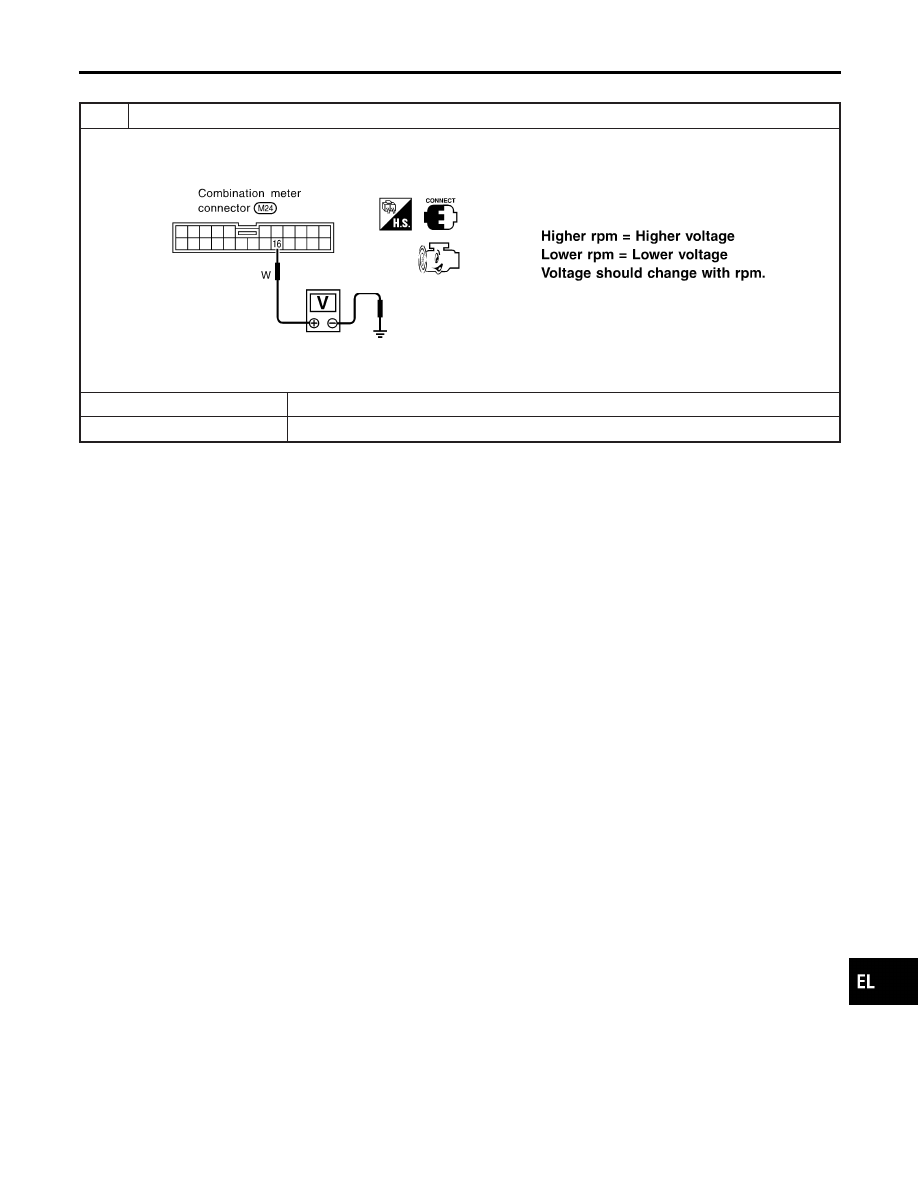
CHECK ECM OUTPUT
1. Start engine.
2. Check voltage between combination meter terminals 16 and ground at idle and 2,000 rpm.
SEL364WB
OK or NG
OK
©
Engine revolution signal is OK.
NG
©
Harness for open or short between ECM and combination meter
GI
MA
EM
LC
EC
FE
AT
TF
PD
AX
SU
BR
ST
RS
BT
HA
SC
IDX
METERS AND GAUGES
Trouble Diagnoses (Cont’d)
EL-105