Infiniti QX4 (R50). Manual - part 287


  Index      Infiniti     Infiniti QX4 (R50) - service repair manual 2001 year


Search            copyright infringement  


Content   ..  285  286  287  288   ..


Infiniti QX4 (R50). Manual - part 287


5

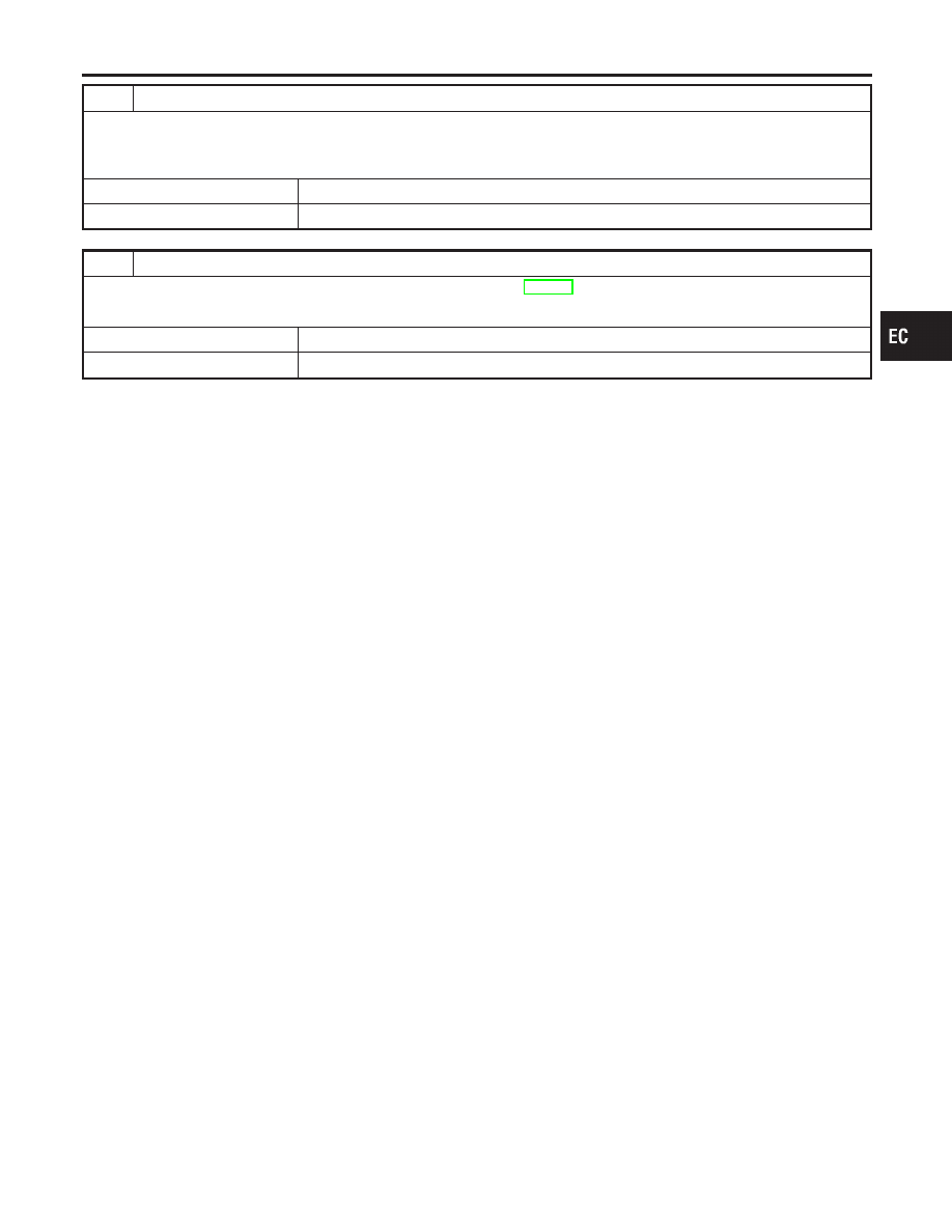
RETEST OVERALL FUNCTION

1. Reconnect harness connectors disconnected.
2. Perform Test No. 1 again.

OK or NG

OK

©

INSPECTION END

NG

©

GO TO 6.

6

CHECK INTERMITTENT INCIDENT

Refer to “TROUBLE DIAGNOSIS FOR INTERMITTENT INCIDENT”, EC-140.

OK or NG

OK

©

Replace VIAS control solenoid valve as intake manifold collector assembly.

NG

©

Repair or replace harness or connectors.

GI

MA

EM

LC

FE

AT

TF

PD

AX

SU

BR

ST

RS

BT

HA

SC

EL

IDX

VARIABLE INDUCTION AIR CONTROL SYSTEM (VIAS)

Diagnostic Procedure (Cont’d)

EC-615

SEF375Z

Component Description

NBEC0383

The fuel injector is a small, precise solenoid valve. When the ECM
supplies a ground to the injector circuit, the coil in the injector is
energized. The energized coil pulls the needle valve back and
allows fuel to flow through the injector into the intake manifold. The
amount of fuel injected depends upon the injection pulse duration.
Pulse duration is the length of time the injector remains open. The
ECM controls the injection pulse duration based on engine fuel
needs.

CONSULT-II Reference Value in Data Monitor
Mode

NBEC0384

Specification data are reference values.

MONITOR ITEM

CONDITION

SPECIFICATION

INJ PULSE-B2
INJ PULSE-B1

I

Engine: After warming up

I

Air conditioner switch: “OFF”

I

Shift lever: “N”

I

No-load

Idle

2.4 - 3.2 msec

2,000 rpm

1.9 - 2.8 msec

B/FUEL SCHDL

ditto

Idle

2.0 - 3.2 msec

2,000 rpm

1.4 - 2.6 msec

ECM Terminals and Reference Value

NBEC0685

Specification data are reference values and are measured between each terminal and ground.

CAUTION:

Do not use ECM ground terminals when measuring input/output voltage. Doing so may result in dam-
age to the ECM’s transistor. Use a ground other than ECM terminals, such as the ground.

TERMI-

NAL

NO.

WIRE

COLOR

ITEM

CONDITION

DATA (DC Voltage)

101
102
103
104
105
107

R/B
L/W
R/W
PU/R
R/Y
R/L

Injector No. 1
Injector No. 5
Injector No. 2
Injector No. 6
Injector No. 3
Injector No. 4

[Engine is running]

I

Idle speed

BATTERY VOLTAGE
(11 - 14V)

INJECTOR

Component Description

EC-616

Wiring Diagram

NBEC0386

MEC974C

GI

MA

EM

LC

FE

AT

TF

PD

AX

SU

BR

ST

RS

BT

HA

SC

EL

IDX

INJECTOR

Wiring Diagram

EC-617

Diagnostic Procedure

NBEC0387

1

INSPECTION START

Turn ignition switch to “START”.
Is any cylinder ignited?

Yes or No

Yes

©

GO TO 2.

No

©

GO TO 3.

2

CHECK OVERALL FUNCTION

With CONSULT-II

1. Start engine.
2. Perform “POWER BALANCE” in “ACTIVE TEST” mode with CONSULT-II.

SEF190Y

3. Make sure that each circuit produces a momentary engine speed drop.

Without CONSULT-II

1. Start engine.
2. Listen to each injector operating sound.

MEC703B

Clicking noise should be heard.

OK or NG

OK

©

INSPECTION END

NG

©

GO TO 3.

INJECTOR

Diagnostic Procedure

EC-618


Content   ..  285  286  287  288   ..