Infiniti QX4 (R50). Manual - part 280
 

  Index      Infiniti     Infiniti QX4 (R50) - service repair manual 2001 year


Search            copyright infringement  


Content   ..  278  279  280  281   ..


Infiniti QX4 (R50). Manual - part 280


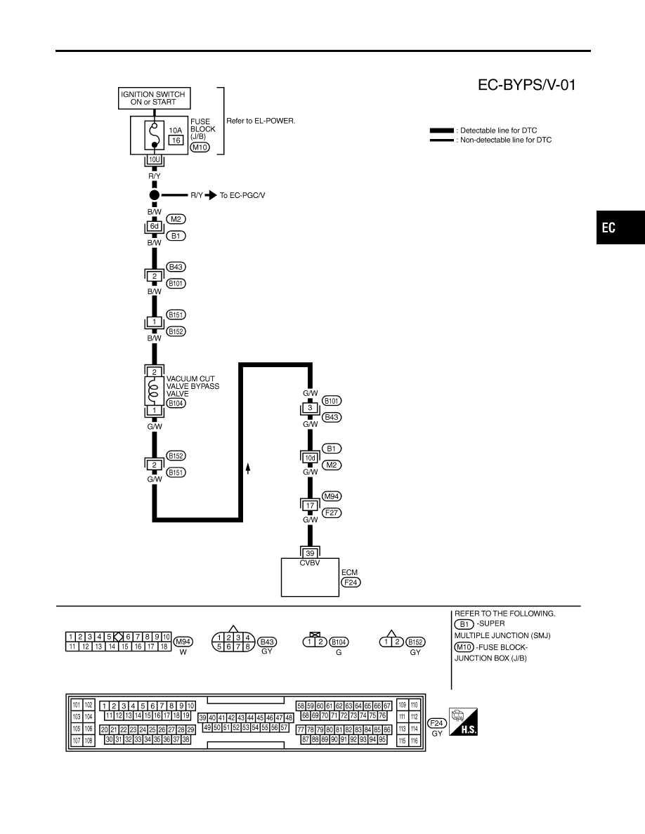
Wiring Diagram

NBEC0351

MEC972C

GI

MA

EM

LC

FE

AT

TF

PD

AX

SU

BR

ST

RS

BT

HA

SC

EL

IDX

DTC P1490 VACUUM CUT VALVE BYPASS VALVE (CIRCUIT)

Wiring Diagram

EC-587

Diagnostic Procedure

NBEC0352

1

INSPECTION START

Do you have CONSULT-II?

Yes or No

Yes

©

GO TO 2.

No

©

GO TO 3.

2

CHECK VACUUM CUT VALVE BYPASS VALVE CIRCUIT

With CONSULT-II

1. Turn ignition switch “OFF” and then “ON”.
2. Select “VC/V BYPASS/V” in “ACTIVE TEST” mode with CONSULT-II.
3. Touch “ON/OFF” on CONSULT-II screen.

SEF014Z

4. Make sure that clicking sound is heard from the vacuum cut valve bypass valve.

OK or NG

OK

©

GO TO 7.

NG

©

GO TO 3.

DTC P1490 VACUUM CUT VALVE BYPASS VALVE (CIRCUIT)

Diagnostic Procedure

EC-588

3

CHECK VACUUM CUT VALVE BYPASS VALUE POWER SUPPLY CIRCUIT

1. Turn ignition switch “OFF”.
2. Disconnect vacuum cut valve bypass valve harness connector.

SEF485T

3. Turn ignition switch “ON”.
4. Check voltage between vacuum cut valve bypass valve terminal 2 and ground with CONSULT-II or tester.

SEF015Z

OK or NG

OK

©

GO TO 5.

NG

©

GO TO 4.

4

DETECT MALFUNCTIONING PART

Check the following.

I

Harness connectors M2, B1

I

Fuse block (J/B) connector M10

I

Harness connectors B43, B101 and B151, B152

I

10A fuse

I

Harness for open or short between vacuum cut valve bypass valve and fuse

©

Repair harness or connectors.

5

CHECK VACUUM CUT VALVE BYPASS VALVE OUTPUT SIGNAL CIRCUIT FOR OPEN AND SHORT

1. Turn ignition switch “OFF”.
2. Disconnect ECM harness connector.
3. Check harness continuity between ECM terminal 39 and vacuum cut valve bypass valve terminal 1. Refer to Wiring

Diagram.

Continuity should exist.

4. Also check harness for short to ground and short to power.

OK or NG

OK

©

GO TO 7.

NG

©

GO TO 6.

GI

MA

EM

LC

FE

AT

TF

PD

AX

SU

BR

ST

RS

BT

HA

SC

EL

IDX

DTC P1490 VACUUM CUT VALVE BYPASS VALVE (CIRCUIT)

Diagnostic Procedure (Cont’d)

EC-589

6

DETECT MALFUNCTIONING PART

Check the following.

I

Harness connectors B152, B151 and B101, B43

I

Harness connectors B1, M2 and M94, F27

I

Harness for open or short between vacuum cut valve bypass valve and ECM

©

Repair open circuit or short to ground or short to power in harness or connectors.

7

CHECK VACUUM CUT VALVE BYPASS VALVE

With CONSULT-II

1. Reconnect harness disconnected connectors.
2. Turn ignition switch ON.
3. Perform “VC/V BYPASS/V” in “ACTIVE TEST” mode.
4. Check air passage continuity and operation delay time under the following conditions.

SEF016Z

Without CONSULT-II

Check air passage continuity and operation delay time under the following conditions.

SEF358X

OK or NG

OK

©

GO TO 8.

NG

©

Replace vacuum cut valve bypass valve.

8

CHECK INTERMITTENT INCIDENT

Refer to “TROUBLE DIAGNOSIS FOR INTERMITTENT INCIDENT”, EC-140.

©

INSPECTION END

DTC P1490 VACUUM CUT VALVE BYPASS VALVE (CIRCUIT)

Diagnostic Procedure (Cont’d)

EC-590


Content   ..  278  279  280  281   ..