Infiniti QX4 (R50). Manual - part 278
 

  Index      Infiniti     Infiniti QX4 (R50) - service repair manual 2001 year


Search            copyright infringement  


Content   ..  276  277  278  279   ..


Infiniti QX4 (R50). Manual - part 278


5

CHECK VACUUM CUT VALVE

1. Turn ignition switch OFF.
2. Remove vacuum cut valve.
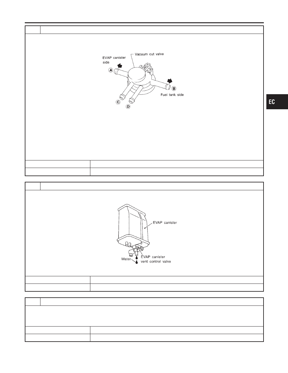
3. Check vacuum cut valve as follows:

SEF379Q

a. Plug port and with fingers.
b. Apply vacuum to port and check that there is no suction from port B.
c. Apply vacuum to port and check that there is suction from port A.
d. Blow air in port and check that there is a resistance to flow out of port A.
e. Open port and D.
f. Blow air in port check that air flows freely out of port C.
g. Blow air in port check that air flows freely out of port D.

OK or NG

OK

©

GO TO 6.

NG

©

Replace vacuum cut valve.

6

CHECK IF EVAP CANISTER SATURATED WITH WATER

1. Remove EVAP canister with EVAP canister vent control valve attached.
2. Check if water will drain from the EVAP canister.

SEF596U

Yes or No

Yes

©

GO TO 7.

No

©

GO TO 9.

7

CHECK EVAP CANISTER

Weigh the EVAP canister with the EVAP canister vent control valve attached.
The weight should be less than 1.8 kg (4.0 lb).

OK or NG

OK

©

GO TO 9.

NG

©

GO TO 8.

GI

MA

EM

LC

FE

AT

TF

PD

AX

SU

BR

ST

RS

BT

HA

SC

EL

IDX

DTC P1448 EVAPORATIVE EMISSION (EVAP) CANISTER VENT CONTROL

VALVE (OPEN)

Diagnostic Procedure (Cont’d)

EC-579

8

DETECT MALFUNCTIONING PART

Check the following.

I

EVAP canister for damage

I

EVAP hose between EVAP canister and water separator for clogging or poor connection

©

Repair hose or replace EVAP canister.

9

CHECK EVAP CONTROL SYSTEM PRESSURE SENSOR HOSE

Check disconnection or improper connection of hose connected to EVAP control system pressure sensor.

OK or NG

OK

©

GO TO 10.

NG

©

Repair it.

10

CHECK EVAP CONTROL SYSTEM PRESSURE SENSOR CONNECTOR

1. Disconnect EVAP control system pressure sensor harness connector.

SEF495R

2. Check connectors for water.

Water should not exist.

OK or NG

OK

©

GO TO 11.

NG

©

Replace EVAP control system pressure sensor.

DTC P1448 EVAPORATIVE EMISSION (EVAP) CANISTER VENT CONTROL

VALVE (OPEN)

Diagnostic Procedure (Cont’d)

EC-580

11

CHECK EVAP CONTROL SYSTEM PRESSURE SENSOR

1. Remove EVAP control system pressure sensor with its harness connector connected.

CAUTION:

I

Never apply force to the air hole protector of the sensor if equipped.

SEF799W

2. Remove hose from EVAP control system pressure sensor.
3. Turn ignition switch “ON”.
4. Use pump to apply vacuum and pressure to EVAP control system pressure sensor as shown in figure.

CAUTION:

I

Always calibrate the vacuum pump gauge when using it.

I

Do not apply below −20 kPa (−150 mmHg, −5.91 inHg) or over 20 kPa (150 mmHg, 5.91 inHg) of pressure.

5. Check input voltage between ECM terminal 84 and ground.

SEF342X

CAUTION:

I

Discard and EVAP control system pressure sensor which has been dropped from a height of more than 0.5 m
(19.7 in) onto a hard surface such as a concrete floor; use a new one.

OK or NG

OK

©

GO TO 12.

NG

©

Replace EVAP control system pressure sensor.

12

CHECK INTERMITTENT INCIDENT

Refer to “TROUBLE DIAGNOSIS FOR INTERMITTENT INCIDENT”, EC-140.

©

INSPECTION END

GI

MA

EM

LC

FE

AT

TF

PD

AX

SU

BR

ST

RS

BT

HA

SC

EL

IDX

DTC P1448 EVAPORATIVE EMISSION (EVAP) CANISTER VENT CONTROL

VALVE (OPEN)

Diagnostic Procedure (Cont’d)

EC-581

SEF018S

Component Description

NBEC0632

The fuel level sensor is mounted in the fuel level sensor unit. The
sensor detects a fuel level in the fuel tank and transmits a signal
to the ECM.
It consists of two parts, one is mechanical float and the other side
is variable resistor. Fuel level sensor output voltage changes
depending on the movement of the fuel mechanical float.

On Board Diagnostic Logic

NBEC0633

ECM receives two signals from the fuel level sensor.
One is fuel level sensor power supply circuit, and the other is fuel
level sensor ground circuit.
This diagnosis indicates the latter to detect open circuit malfunc-
tion. Malfunction is detected when a high voltage from the sensor
is sent to ECM.

Possible Cause

NBEC0634

I

Fuel level sensor circuit
(The fuel level sensor circuit is open or shorted.)

DTC Confirmation Procedure

NBEC0635

NOTE:
If “DTC Confirmation Procedure” has been previously conducted,
always turn ignition switch “OFF” and wait at least 10 seconds
before conducting the next test.

SEF195Y

WITH CONSULT-II

NBEC0635S01

1)

Turn ignition switch “ON”.

2)

Select “DATA MONITOR” mode with CONSULT-II.

3)

Wait at least 5 seconds.

4)

If 1st trip DTC is detected, go to “Diagnostic Procedure”,
EC-584.

WITH GST

NBEC0635S02

Follow the procedure “WITH CONSULT-II” above.

DTC P1464 FUEL LEVEL SENSOR CIRCUIT (GROUND SIGNAL)

Component Description

EC-582


Content   ..  276  277  278  279   ..