Infiniti QX4 (R50). Manual - part 186


  Index      Infiniti     Infiniti QX4 (R50) - service repair manual 2001 year


Search            copyright infringement  


Content   ..  184  185  186  187   ..


Infiniti QX4 (R50). Manual - part 186


TERMI-

NAL

NO.

WIRE

COLOR

ITEM

CONDITION

DATA (DC Voltage)

62

G/B

Heated oxygen sensor
1 (front) (bank 2)

[Engine is running]

I

Warm-up condition

I

Engine speed is 2,000 rpm.

0 - Approximately 1.0V (Peri-
odically change)

SEF059V

SEF299U

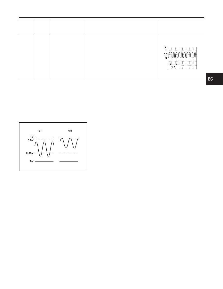
On Board Diagnosis Logic

NBEC0104

To judge the malfunction, the output from the heated oxygen sen-
sor 1 (front) is monitored to determine whether the “rich” output is
sufficiently high. The “lean” output is sufficiently low. When both the
outputs are shifting to the rich side, the malfunction will be
detected.
Malfunction is detected when the maximum and minimum voltages
from the sensor are beyond the specified voltages.

Possible Cause

NBEC0434

I

Heated oxygen sensor 1 (front)

I

Fuel pressure

I

Injectors

I

Heated oxygen sensor 1 heater (front)

DTC Confirmation Procedure

NBEC0105

CAUTION:

Always drive vehicle at a safe speed.
NOTE:
If “DTC Confirmation Procedure” has been previously conducted,
always turn ignition switch “OFF” and wait at least 10 seconds
before conducting the next test.
TESTING CONDITION:

I

Always perform at a temperature above −10°C (14°F).

I

Before performing the following procedure, confirm that
battery voltage is more than 11V at idle.

GI

MA

EM

LC

FE

AT

TF

PD

AX

SU

BR

ST

RS

BT

HA

SC

EL

IDX

DTC P0132, P0152 HEATED OXYGEN SENSOR 1 (FRONT) (BANK 1)/(BANK 2)

(RICH SHIFT MONITORING)

ECM Terminals and Reference Value (Cont’d)

EC-211

SEF336Z

SEF337Z

SEF655Y

WITH CONSULT-II

NBEC0105S01

1)

Start engine and warm it up to normal operating temperature.

2)

Stop engine and wait at least 5 seconds.

3)

Turn ignition switch “ON” and select “HO2S1 (B1)/(B2) P0132/
P0152” of “HO2S1” in “DTC WORK SUPPORT” mode with
CONSULT-II.

4)

Touch “START”.

5)

Start engine and let it idle for at least 3 minutes.

NOTE:
Never raise engine speed above 3,600 rpm after this step. If
the engine speed limit is exceeded, return to step 5.
6)

When the following conditions are met, “TESTING” will be dis-
played on the CONSULT-II screen. Maintain the conditions
continuously until “TESTING” changes to “COMPLETED”. (It
will take approximately 50 seconds or more.)

ENG SPEED

1,300 - 2,800 rpm

Vehicle speed

80 - 100 km/h (50 - 62 MPH)

B/FUEL SCHDL

3 - 10 msec

Selector lever

Suitable position

If “TESTING” is not displayed after 5 minutes, retry from
step 2.

7)

Make sure that “OK” is displayed after touching “SELF-DIAG
RESULTS”.

If

“NG”

is

displayed,

refer

to

“Diagnostic

Procedure”, EC-213.

SEF308XB

Overall Function Check

NBEC0106

Use this procedure to check the overall function of the heated oxy-
gen sensor 1 (front) circuit. During this check, a 1st trip DTC might
not be confirmed.

WITH GST

NBEC0106S01

1)

Start engine and warm it up to normal operating temperature.

2)

Set voltmeter probes between ECM terminal 63 (HO2S1 bank
1 right signal) or 62 (HO2S1 bank 2 left signal) and engine
ground.

3)

Check one of the following with engine speed held at 2,000
rpm constant under no load.

I

The maximum voltage is below 0.8V at least one time.

I

The minimum voltage is below 0.35V at least one time.

4)

If NG, go to “Diagnostic Procedure”, EC-213.

DTC P0132, P0152 HEATED OXYGEN SENSOR 1 (FRONT) (BANK 1)/(BANK 2)

(RICH SHIFT MONITORING)

DTC Confirmation Procedure (Cont’d)

EC-212

Diagnostic Procedure

NBEC0107

1

RETIGHTEN GROUND SCREWS

1. Turn ignition switch “OFF”.
2. Loosen and retighten engine ground screws.

SEF959Y

©

GO TO 2.

2

RETIGHTEN HEATED OXYGEN SENSOR 1 (FRONT)

Loosen and retighten corresponding heated oxygen sensor 1 (front).

Tightening torque:

40 - 60 N·m (4.1 - 6.1 kg-m, 30 - 44 ft-lb)

©

GO TO 3.

GI

MA

EM

LC

FE

AT

TF

PD

AX

SU

BR

ST

RS

BT

HA

SC

EL

IDX

DTC P0132, P0152 HEATED OXYGEN SENSOR 1 (FRONT) (BANK 1)/(BANK 2)

(RICH SHIFT MONITORING)

Diagnostic Procedure

EC-213

3

CLEAR THE SELF-LEARNING DATA

With CONSULT-II

1. Start engine and warm it up to normal operating temperature.
2. Select “SELF-LEARNING CONT” in “WORK SUPPORT” mode with CONSULT-II.
3. Clear the self-learning control coefficient by touching “CLEAR”.

SEF968Y

4. Run engine for at least 10 minutes at idle speed.

Is the 1st trip DTC P0172 or P0175 detected?
Is it difficult to start engine?

Without CONSULT-II

1. Start engine and warm it up to normal operating temperature.
2. Turn ignition switch “OFF”.
3. Disconnect mass air flow sensor harness connector, and restart and run engine for at least 5 seconds at idle speed.
4. Stop engine and reconnect mass air flow sensor harness connector.
5. Make sure 1st trip DTC P0100 is displayed.
6. Erase the 1st trip DTC memory. Refer to “HOW TO ERASE EMISSION-RELATED DIAGNOSTIC INFORMATION”,

EC-72.

7. Make sure DTC P0000 is displayed.
8. Run engine for at least 10 minutes at idle speed.

Is the 1st trip DTC P0172 or P0175 detected?
Is it difficult to start engine?

Yes or No

Yes

©

Perform trouble diagnosis for DTC P0172, P0175. Refer to EC-302.

No

©

GO TO 4.

4

CHECK HO2S 1 (FRONT) CONNECTOR FOR WATER

1. Turn ignition switch “OFF”.
2. Check heated oxygen sensor 1 (front) harness protector color.

SEF505Y

3. Disconnect heated oxygen sensor 1 (front) harness connector.
4. Check connectors for water.

Water should not exist.

OK or NG

OK

©

GO TO 5.

NG

©

Repair or replace harness or connectors.

DTC P0132, P0152 HEATED OXYGEN SENSOR 1 (FRONT) (BANK 1)/(BANK 2)

(RICH SHIFT MONITORING)

Diagnostic Procedure (Cont’d)

EC-214


Content   ..  184  185  186  187   ..