Infiniti QX4 (R50). Manual - part 185


  Index      Infiniti     Infiniti QX4 (R50) - service repair manual 2001 year


Search            copyright infringement  


Content   ..  183  184  185  186   ..


Infiniti QX4 (R50). Manual - part 185


4

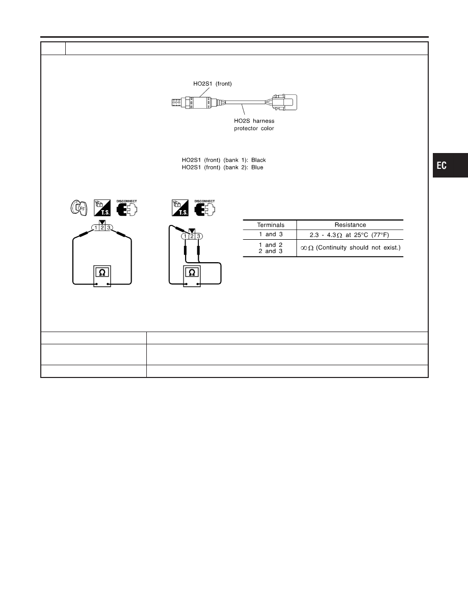
CHECK HEATED OXYGEN SENSOR HEATER 1 (FRONT)

1. Stop engine.
2. Check heated oxygen sensor 1 (front) harness protector color.

SEF505Y

3. Disconnect HO2S1 harness connector.
4. Check resistance between HO2S1 terminals as follows.

SEF969Y

CAUTION:

Discard any heated oxygen sensor which has been dropped from a height of more than 0.5 m (19.7 in) onto a
hard surface such as a concrete floor; use a new one.

OK or NG

OK (With CONSULT-II)

©

GO TO 5.

OK (Without CONSULT-
II)

©

GO TO 6.

NG

©

GO TO 7.

GI

MA

EM

LC

FE

AT

TF

PD

AX

SU

BR

ST

RS

BT

HA

SC

EL

IDX

DTC P0131, P0151 HEATED OXYGEN SENSOR 1 (FRONT) (BANK 1)/(BANK 2)

(LEAN SHIFT MONITORING)

Diagnostic Procedure (Cont’d)

EC-207

5

CHECK HEATED OXYGEN SENSOR 1 (FRONT)

With CONSULT-II

1. Start engine and warm it up to normal operating temperature.
2. Select “MANU TRIG” and adjust “TRIGGER POINT” to 100% in “DATA MONITOR” mode with CONSULT-II.
3. Select “HO2S1 (B1)/(B2)” and “HO2S1 MNTR (B1)/(B2)”.
4. Hold engine speed at 2,000 rpm under no load during the following steps.
5. Touch “RECORD” on CONSULT-II screen.

SEF967Y

6. Check the following.

I

“HO2S1 MNTR (B1)/(B2)” in “DATA MONITOR” mode changes from “RICH” to “LEAN” to “RICH” 5 times in 10 seconds.
5 times (cycles) are counted as shown below.

SEF647Y

I

“HO2S1 (B1)/(B2)” voltage goes above 0.6V at least once.

I

“HO2S1 (B1)/(B2)” voltage goes below 0.3V at least once.

I

“HO2S1 (B1)/(B2)” voltage never exceeds 1.0V.

SEF648Y

CAUTION:

Discard any heated oxygen sensor which has been dropped from a height of more than 0.5 m (19.7 in) onto a
hard surface such as a concrete floor; use a new one.

OK or NG

OK

©

GO TO 8.

NG

©

GO TO 7.

DTC P0131, P0151 HEATED OXYGEN SENSOR 1 (FRONT) (BANK 1)/(BANK 2)

(LEAN SHIFT MONITORING)

Diagnostic Procedure (Cont’d)

EC-208

6

CHECK HEATED OXYGEN SENSOR 1 (FRONT)

Without CONSULT-II

1. Start engine and warm it up to normal operating temperature.
2. Set voltmeter probes between ECM terminal 63 (HO2S1 bank 1 right signal) or 62 (HO2S1 bank 2 left signal) and

engine ground.

3. Check the following with engine speed held at 2,000 rpm constant under no load.

SEF967XA

CAUTION:

Discard any heated oxygen sensor which has been dropped from a height of more than 0.5 m (19.7 in) onto a
hard surface such as a concrete floor; use a new one.

OK or NG

OK

©

GO TO 8.

NG

©

GO TO 7.

7

REPLACE FRONT HEATED OXYGEN SENSOR

1. Turn ignition switch “OFF”.
2. Check heated oxygen sensor 1 (front) harness protector color.

SEF505Y

CAUTION:

Before installing new oxygen sensor, clean exhaust system threads using Oxygen Sensor Thread Cleaner tool
J-43897-18 or J-43897-12 and approved anti-seize lubricant.

©

Replace malfunctioning heated oxygen sensor 1 (front).

8

CHECK INTERMITTENT INCIDENT

Refer to “TROUBLE DIAGNOSIS FOR INTERMITTENT INCIDENT”, EC-140.
For circuit, refer to “DTC P0130 (RIGHT BANK 1), P0150 (LEFT BANK 2) HEATED OXYGEN SENSOR 1 (FRONT)
[HO2S1 (FRONT) (BANK 1)/(BANK 2)] (CIRCUIT)”, EC-192.

©

INSPECTION END

GI

MA

EM

LC

FE

AT

TF

PD

AX

SU

BR

ST

RS

BT

HA

SC

EL

IDX

DTC P0131, P0151 HEATED OXYGEN SENSOR 1 (FRONT) (BANK 1)/(BANK 2)

(LEAN SHIFT MONITORING)

Diagnostic Procedure (Cont’d)

EC-209

SEF463R

SEF288D

Component Description

NBEC0101

The heated oxygen sensor 1 (front) is placed into the front tube. It
detects the amount of oxygen in the exhaust gas compared to the
outside air. The heated oxygen sensor 1 (front) has a closed-end
tube made of ceramic zirconia. The zirconia generates voltage from
approximately 1V in richer conditions to 0V in leaner conditions.
The heated oxygen sensor 1 (front) signal is sent to the ECM. The
ECM adjusts the injection pulse duration to achieve the ideal air-
fuel ratio. The ideal air-fuel ratio occurs near the radical change
from 1V to 0V.

CONSULT-II Reference Value in Data Monitor
Mode

NBEC0102

Specification data are reference values.

MONITOR ITEM

CONDITION

SPECIFICATION

HO2S1 (B1)
HO2S1 (B2)

I

Engine: After warming up

Maintaining engine speed at 2,000
rpm

0 - 0.3V

+,

Approx. 0.6 - 1.0V

HO2S1 MNTR
(B1)
HO2S1 MNTR
(B2)

LEAN

+,

RICH

Changes more than 5 times during
10 seconds.

ECM Terminals and Reference Value

NBEC0654

Specification data are reference values and are measured between each terminal and ground.

CAUTION:

Do not use ECM ground terminals when measuring input/output voltage. Doing so may result in dam-
age to the ECM’s transistor. Use a ground other than ECM terminals, such as the ground.

TERMI-

NAL

NO.

WIRE

COLOR

ITEM

CONDITION

DATA (DC Voltage)

63

G

Heated oxygen sensor
1 (front) (bank 1)

[Engine is running]

I

Warm-up condition

I

Engine speed is 2,000 rpm.

0 - Approximately 1.0V (Peri-
odically change)

SEF059V

DTC P0132, P0152 HEATED OXYGEN SENSOR 1 (FRONT) (BANK 1)/(BANK 2)

(RICH SHIFT MONITORING)

Component Description

EC-210


Content   ..  183  184  185  186   ..