Infiniti QX4 (R50). Manual - part 177
ECM Terminals and Reference Value
=NBEC0651
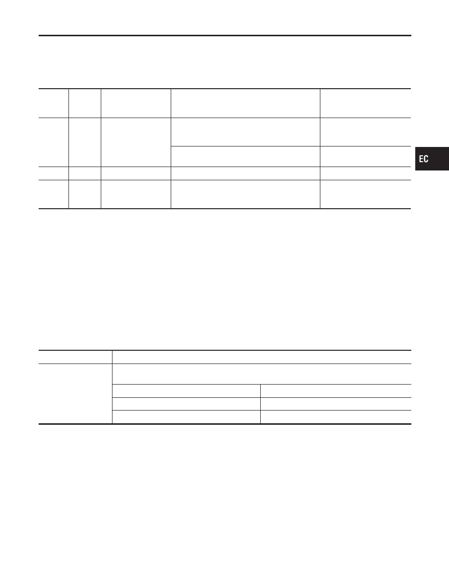
Specification data are reference values and are measured between each terminal and ground.
CAUTION:
Do not use ECM ground terminals when measuring input/output voltage. Doing so may result in dam-
age to the ECM’s transistor. Use a ground other than ECM terminals, such as the ground.
TERMI-
NAL
NO.
WIRE
COLOR
ITEM
CONDITION
DATA (DC Voltage)
91
R
Throttle position sensor
[Engine is running]
I
Warm-up condition
I
Accelerator pedal fully released
0.15 - 0.85V
[Ignition switch “ON”]
I
Accelerator pedal fully depressed
3.5 - 4.7V
111
P/B
Sensors’ power supply
[Ignition switch “ON”]
Approximately 5V
58
B/P
Sensors’ ground
[Engine is running]
I
Warm-up condition
I
Idle speed
Approximately 0V
On Board Diagnosis Logic
NBEC0077
Malfunction is detected when
(Malfunction A) an excessively low or high voltage from the sen-
sor is sent to ECM,
(Malfunction B) a high voltage from the sensor is sent to ECM
under light load driving conditions,
(Malfunction C) a low voltage from the sensor is sent to ECM
under heavy load driving conditions.
FAIL-SAFE MODE
NBEC0077S02
When the malfunction A is detected, the ECM enters fail-safe mode
and the MIL lights up.
Detected items
Engine operating condition in fail-safe mode
Throttle position sensor
circuit
Throttle position will be determined based on the injected fuel amount and the engine speed.
Therefore, acceleration will be poor.
Condition
Driving condition
When engine is idling
Normal
When accelerating
Poor acceleration
Possible Cause
NBEC0430
MALFUNCTION A
NBEC0430S01
I
Harness or connectors
(The throttle position sensor circuit is open or shorted.)
I
Throttle position sensor
MALFUNCTION B
NBEC0430S02
I
Harness or connectors
(The throttle position sensor circuit is open or shorted.)
I
Throttle position sensor
I
Fuel injector
GI
MA
EM
LC
FE
AT
TF
PD
AX
SU
BR
ST
RS
BT
HA
SC
EL
IDX
DTC P0120 THROTTLE POSITION SENSOR
ECM Terminals and Reference Value
EC-175