Infiniti QX4 (R50). Manual - part 178
SEF305X
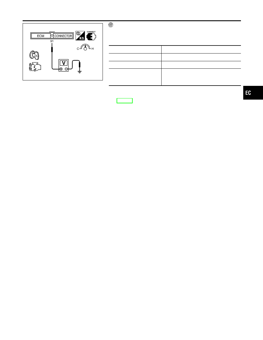
With GST
=NBEC0078S0302
1)
Start engine and warm it up to normal operating temperature.
2)
Maintain the following conditions for at least 10 consecutive
seconds.
Gear position
Suitable position
Engine speed
More than 2,000 rpm
Engine coolant temperature
More than 70°C (158°F)
Voltage between ECM termi-
nal 91 (Mass air flow sensor
signal) and ground
More than 3.2V
3)
Select “MODE 7” with GST.
4)
If 1st trip DTC is detected, go to “Diagnostic Procedure”,
EC-181.
GI
MA
EM
LC
FE
AT
TF
PD
AX
SU
BR
ST
RS
BT
HA
SC
EL
IDX
DTC P0120 THROTTLE POSITION SENSOR
DTC Confirmation Procedure (Cont’d)
EC-179