Infiniti QX4 (R50). Manual - part 176
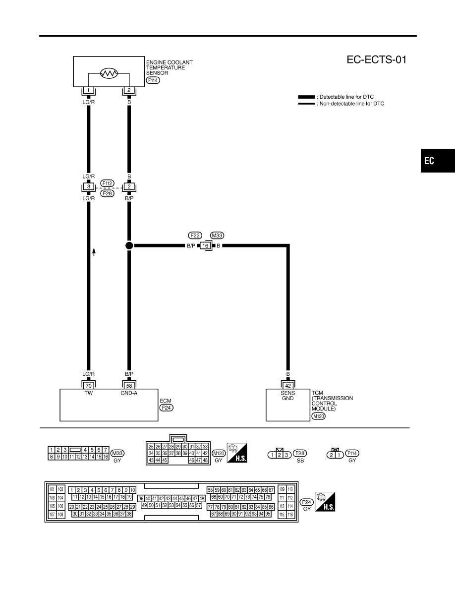
Wiring Diagram
NBEC0072
MEC945C
GI
MA
EM
LC
FE
AT
TF
PD
AX
SU
BR
ST
RS
BT
HA
SC
EL
IDX
DTC P0115 ENGINE COOLANT TEMPERATURE SENSOR (ECTS) (CIRCUIT)
Wiring Diagram
EC-171
|
|
|
Wiring Diagram NBEC0072 MEC945C GI MA EM LC FE AT TF PD AX SU BR ST RS BT HA SC EL IDX DTC P0115 ENGINE COOLANT TEMPERATURE SENSOR (ECTS) (CIRCUIT) Wiring Diagram EC-171 |