Infiniti QX4 (R50). Manual - part 172


  Index      Infiniti     Infiniti QX4 (R50) - service repair manual 2001 year


Search            copyright infringement  


Content   ..  170  171  172  173   ..


Infiniti QX4 (R50). Manual - part 172


Diagnostic Procedure

NBEC0057

1

INSPECTION START

Which malfunction (A, B, C, D or E) is duplicated?

MTBL0373

Type I or Type II

Type I

©

GO TO 3.

Type II

©

GO TO 2.

2

CHECK INTAKE SYSTEM

Check the following for connection.

I

Air duct

I

Vacuum hoses

I

Intake air passage between air duct to intake manifold collector

OK or NG

OK

©

GO TO 3.

NG

©

Reconnect the parts.
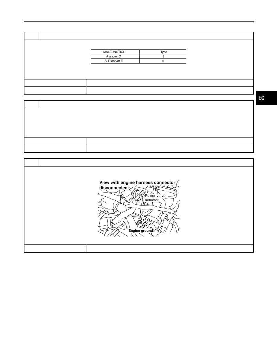
3

RETIGHTEN GROUND SCREWS

1. Turn ignition switch “OFF”.
2. Loosen and retighten engine ground screws.

SEF959Y

©

GO TO 4.

GI

MA

EM

LC

FE

AT

TF

PD

AX

SU

BR

ST

RS

BT

HA

SC

EL

IDX

DTC P0100 MASS AIR FLOW SENSOR (MAFS)

Diagnostic Procedure

EC-155

4

CHECK MAFS POWER SUPPLY CIRCUIT

1. Disconnect mass air flow sensor (MAFS) harness connector.

SEF960Y

2. Turn ignition switch “ON”.
3. Check voltage between MAFS terminals 2, 4 and ground with CONSULT-II or tester.

SEF297X

OK or NG

OK

©

GO TO 6.

NG

©

GO TO 5.

5

DETECT MALFUNCTIONING PART

Check the following.

I

Harness for open or short between ECM relay and mass air flow sensor

I

Harness for open or short between mass air flow sensor and ECM

©

Repair harness or connectors.

6

CHECK MAFS GROUND CIRCUIT FOR OPEN AND SHORT

1. Turn ignition switch “OFF”.
2. Disconnect ECM harness connector.
3. Check harness continuity between MAFS terminal 3 and ECM terminal 73.

Refer to Wiring Diagram.

Continuity should exist.

4. Also check harness for short to power.

OK or NG

OK

©

GO TO 7.

NG

©

Repair open circuit or short to power in harness or connectors.

DTC P0100 MASS AIR FLOW SENSOR (MAFS)

Diagnostic Procedure (Cont’d)

EC-156

7

CHECK MAFS INPUT SIGNAL CIRCUIT FOR OPEN AND SHORT

1. Check harness continuity between MAFS terminal 1 and ECM terminal 61.

Refer to Wiring Diagram.

Continuity should exist.

2. Also check harness for short to ground and short to power.

OK or NG

OK

©

GO TO 8.

NG

©

Repair open circuit or short to ground or short to power in harness or connectors.

8

CHECK MASS AIR FLOW SENSOR

1. Reconnect harness connectors disconnected.
2. Start engine and warm it up to normal operating temperature.
3. Check voltage between ECM terminal 61 (Mass air flow sensor signal) and ground.

SEF298X

4. If the voltage is out of specification, disconnect MAFS harness connector and connect it again.

Then repeat above check.

OK or NG

OK

©

GO TO 9.

NG

©

Replace mass air flow sensor.

9

CHECK INTERMITTENT INCIDENT

Refer to “TROUBLE DIAGNOSIS FOR INTERMITTENT INCIDENT”, EC-140.

©

INSPECTION END

GI

MA

EM

LC

FE

AT

TF

PD

AX

SU

BR

ST

RS

BT

HA

SC

EL

IDX

DTC P0100 MASS AIR FLOW SENSOR (MAFS)

Diagnostic Procedure (Cont’d)

EC-157

SEF052V

SEF946SB

Component Description

NBEC0725

The absolute pressure sensor detects ambient barometric pressure
and sends the voltage signal to the ECM. As the pressure
increases, the voltage rises.

ECM Terminals and Reference Value

NBEC0726

Specification data are reference values and are measured between each terminal and ground.

CAUTION:

Do not use ECM ground terminals when measuring input/output voltage. Doing so may result in dam-
age to the ECM’s transistor. Use a ground other than ECM terminals, such as the ground.

TERMI-

NAL

NO.

WIRE

COLOR

ITEM

CONDITION

DATA (DC Voltage)

80

L/R

Absolute pressure sen-
sor

[Ignition switch “ON”]

Approximately 4.4V

111

P/B

Sensors’ power supply

[Ignition switch “ON”]

Approximately 5V

58

B/P

Sensors’ ground

[Engine is running]

I

Warm-up condition

I

Idle speed

Approximately 0V

On Board Diagnosis Logic

NBEC0727

Malfunction is detected when an excessively low or high voltage
from the sensor is sent to ECM.

DTC P0105 ABSOLUTE PRESSURE SENSOR

Component Description

EC-158


Content   ..  170  171  172  173   ..