Infiniti QX4 (R50). Manual - part 103
SBR020B
Thickness
NBBR0035S0202
Thickness variation (At least 8 positions):
Maximum 0.015 mm (0.0006 in)
If thickness variation exceeds the specification, turn rotor with on-
car brake lathe.
Rotor repair limit:
26.0 mm (1.024 in)
SBR574
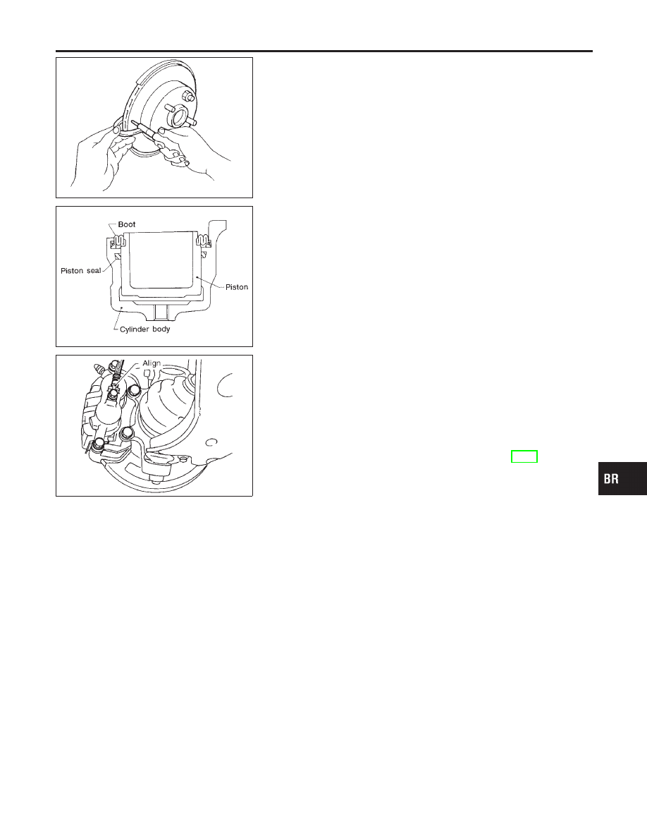
Assembly
NBBR0036
1.
Insert piston seal into groove on cylinder body.
2.
With piston boot fitted to piston, insert piston boot into groove
on cylinder body and install piston.
3.
Properly secure piston boot
SBR387D
Installation
NBBR0037
CAUTION:
I
Refill with new brake fluid “DOT 3”.
I
Never reuse drained brake fluid.
1.
Install caliper assembly.
2.
Install brake hose to caliper securely.
3.
Install all parts and secure all bolts.
4.
Bleed air. Refer to “Bleeding Brake System”, BR-8.
Brake Burnishing Procedure
NBBR0086
When experiencing soft brake pedal feel at very low mileage, or
after replacing the rotor, burnish the brake pad contact surfaces
according to the following procedures.
CAUTION:
Only perform this procedure under safe road and traffic con-
ditions. Use extreme caution.
1.
Drive the vehicle on a straight smooth road at 50 km/h (31
MPH).
2.
Use medium brake pedal/foot effort to bring the vehicle to a
complete stop from 50 km/h (31 MPH). Adjust brake pedal/foot
pressure such that vehicle stopping time equals 3 to 5 sec-
onds.
3.
To cool the brake system, drive the vehicle at 50 km/h (31
MPH) for 1 minute without stopping.
4.
Repeat steps 1 to 3 10 times or more to complete the burnish-
ing procedure.
GI
MA
EM
LC
EC
FE
AT
TF
PD
AX
SU
ST
RS
BT
HA
SC
EL
IDX
FRONT DISC BRAKE
Inspection (Cont’d)
BR-25