Infiniti QX4 (R50). Manual - part 101
SBR231C
2.
Remove piston stopper while piston is pushed into cylinder.
3.
Remove piston assemblies.
If it is difficult to remove secondary piston assembly, gradu-
ally apply compressed air through fluid outlet.
4.
Draw out reservoir tank.
Inspection
NBBR0021
Check master cylinder inner wall for pin holes or scratches.
Replace if damaged.
SBR354C
Assembly
NBBR0022
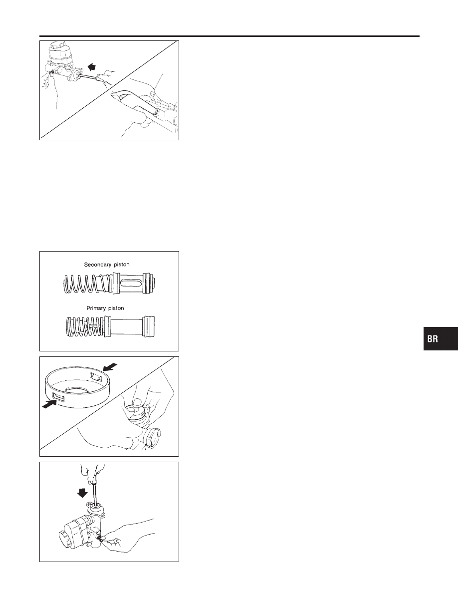
1.
Insert secondary piston assembly. Then insert primary piston
assembly.
I
Pay attention to direction of piston cups in figure at left.
Also, insert pistons squarely to avoid scratches on cylin-
der bore.
I
Pay attention to alignment of secondary piston slit with
valve stopper mounting hole of cylinder body.
SBR940A
2.
Install stopper cap.
Before installing stopper cap, ensure that claws are bent
inward.
3.
Push reservoir tank seals into cylinder body.
4.
Push reservoir tank into cylinder body.
SBR435B
5.
Install valve stopper while piston is pushed into cylinder.
GI
MA
EM
LC
EC
FE
AT
TF
PD
AX
SU
ST
RS
BT
HA
SC
EL
IDX
MASTER CYLINDER
Disassembly (Cont’d)
BR-17