Infiniti QX4 (R50). Manual - part 99
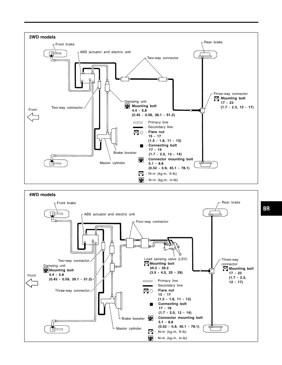
Hydraulic Circuit
NBBR0010
SBR374DA
SBR375DE
GI
MA
EM
LC
EC
FE
AT
TF
PD
AX
SU
ST
RS
BT
HA
SC
EL
IDX
BRAKE HYDRAULIC LINE
Hydraulic Circuit
BR-9
|
|
|
Hydraulic Circuit NBBR0010 SBR374DA SBR375DE GI MA EM LC EC FE AT TF PD AX SU ST RS BT HA SC EL IDX BRAKE HYDRAULIC LINE Hydraulic Circuit BR-9 |