Infiniti QX4 (R50). Manual - part 13


  Index      Infiniti     Infiniti QX4 (R50) - service repair manual 2001 year


Search            copyright infringement  


Content   ..  11  12  13  14   ..


Infiniti QX4 (R50). Manual - part 13


3

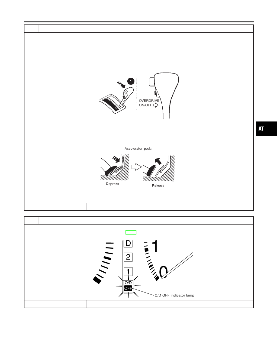
JUDGEMENT PROCEDURE STEP 2

1. Move selector lever to “1” position.
2. Release the overdrive control switch.
3. Depress and release the overdrive control switch (the O/D OFF indicator lamp will be “ON”).
4. Depress and release the overdrive control switch (the O/D OFF indicator lamp will be “OFF”).
5. Depress and hold the overdrive control switch (the O/D OFF indicator lamp will be “ON”) until directed to release the

switch.

SAT970I

6. Depress accelerator pedal fully and release it.
7. Release the overdrive control switch (the O/D OFF indicator lamp will begin to flash “ON” and “OFF”).

SAT981F

©

GO TO 4.

4

CHECK SELF-DIAGNOSIS CODE

Check O/D OFF indicator lamp.
Refer to JUDGEMENT OF SELF-DIAGNOSIS CODE, AT-50.

SAT133K

©

DIAGNOSIS END

GI

MA

EM

LC

EC

FE

TF

PD

AX

SU

BR

ST

RS

BT

HA

SC

EL

IDX

ON BOARD DIAGNOSTIC SYSTEM DESCRIPTION

Diagnostic Procedure Without CONSULT-II (Cont’d)

AT-49

JUDGEMENT OF SELF-DIAGNOSIS CODE

NBAT0206S04

O/D OFF indicator lamp:

All judgement flickers are same.

SAT666I

All circuits that can be confirmed by self-diagnosis are OK.

1st judgement flicker is longer than others.

SAT667I

Revolution sensor circuit is short-circuited or disconnected.

Go to DTC P0720 VEHICLE SPEED SENSOR·A/T (REVO-

LUTION SENSOR), AT-111.

2nd judgement flicker is longer than others.

SAT668I

Vehicle speed sensor circuit is short-circuited or disconnected.

Go to DTC VEHICLE SPEED SENSOR·MTR, AT-197.

3rd judgement flicker is longer than others.

SAT669I

Throttle position sensor circuit is short-circuited or disconnected.

Go to DTC P1705 THROTTLE POSITION SENSOR,

AT-176.

4th judgement flicker is longer than others.

SAT670I

Shift solenoid valve A circuit is short-circuited or disconnected.

Go to DTC P0750 SHIFT SOLENOID VALVE A, AT-168.

5th judgement flicker is longer than others.

SAT671I

Shift solenoid valve B circuit is short-circuited or disconnected.

Go to DTC P0755 SHIFT SOLENOID VALVE B, AT-172.

ON BOARD DIAGNOSTIC SYSTEM DESCRIPTION

Diagnostic Procedure Without CONSULT-II (Cont’d)

AT-50

O/D OFF indicator lamp:

6th judgement flicker is longer than others.

SAT672I

Overrun clutch solenoid valve circuit is short-circuited or discon-
nected.

Go to DTC P1760 OVERRUN CLUTCH SOLENOID VALVE,

AT-185.

7th judgement flicker is longer than others.

SAT673I

Torque converter clutch solenoid valve circuit is short-circuited
or disconnected.

Go to DTC P0740 TORQUE CONVERTER CLUTCH SOLE-

NOID VALVE, AT-148.

8th judgement flicker is longer than others.

SAT674I

A/T fluid temperature sensor is disconnected or TCM power
source circuit is damaged.

Go to DTC BATT/FLUID TEMP SEN (A/T FLUID TEM-

PERATURE SENSOR AND TCM POWER SOURCE), AT-190.

9th judgement flicker is longer than others.

SAT675I

Engine speed signal circuit is short-circuited or disconnected.

Go to DTC P0725 ENGINE SPEED SIGNAL, AT-116.

10th judgement flicker is longer than others.

SAT676I

Turbine revolution sensor circuit is short-circuited or discon-
nected.

Go to DTC Turbine Revolution Sensor, AT-202.

11th judgement flicker is longer than others.

SAT677I

Line pressure solenoid valve circuit is short-circuited or discon-
nected.

Go to DTC P0745 LINE PRESSURE SOLENOID VALVE,

AT-162.

GI

MA

EM

LC

EC

FE

TF

PD

AX

SU

BR

ST

RS

BT

HA

SC

EL

IDX

ON BOARD DIAGNOSTIC SYSTEM DESCRIPTION

Diagnostic Procedure Without CONSULT-II (Cont’d)

AT-51

O/D OFF indicator lamp:

12th judgement flicker is longer than others.

SAT678I

The ECM-A/T communication line is open or shorted.

Go to DTC A/T Communication Line, AT-207.

Flickers as shown below.

SAT679I

Battery power is low.
Battery has been disconnected for a long time.
Battery is connected conversely.
(When reconnecting TCM connectors. — This is not a problem.)

Lamp comes on.

SAT367J

PNP switch, overdrive control switch or throttle position switch
circuit is disconnected or TCM is damaged.

Go to 21. TCM Self-diagnosis Does Not Activate (PNP,

OVERDRIVE CONTROL AND THROTTLE POSITION
SWITCHES), AT-257.

t

1

= 2.5 seconds

t

2

= 2.0 seconds

t

3

= 1.0 second

t

4

= 1.0 second

ON BOARD DIAGNOSTIC SYSTEM DESCRIPTION

Diagnostic Procedure Without CONSULT-II (Cont’d)

AT-52


Content   ..  11  12  13  14   ..