Infiniti Q45 (FY33). Manual - part 542


  Index      Infiniti     Infiniti Q45 (FY33) - service repair manual 2001 year


Search            copyright infringement  


Content   ..  540  541  542  543   ..


Infiniti Q45 (FY33). Manual - part 542


PINION ASSEMBLY

I

Thoroughly examine pinion gear. If pinion gear is damaged,
cracked or worn, replace it.

I

Check that all bearings roll freely. Ensure that balls, rollers and
races are not cracked, pitted or worn. Replace if necessary.

SST333B

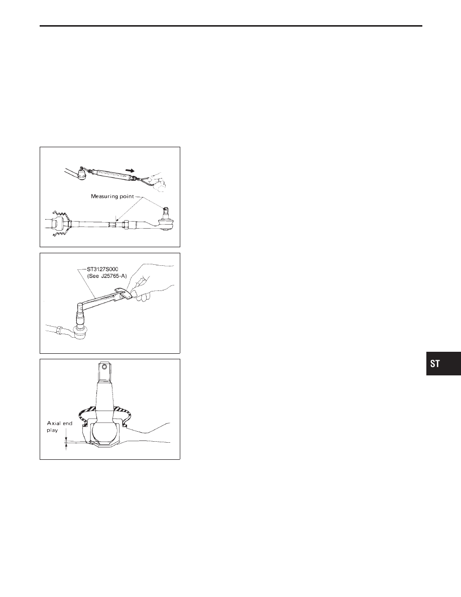
TIE-ROD OUTER AND INNER SOCKET

I

Check ball joint for swinging force.

Tie-rod outer ball joint:

4.9 - 46.1 N
(0.5 - 4.7 kg, 1.1 - 10.4 lb)

Tie-rod inner ball joint:

7.8 - 65.7 N
(0.8 - 6.7 kg, 1.8 - 14.8 lb)

SST882B

I

Check ball joint for rotating torque.

Tie-rod outer ball joint:

0.29 - 2.94 N

m

(3.0 - 30.0 kg-cm, 2.6 - 26.0 in-lb)

Tie-rod inner ball joint:

1.0 - 7.8 N

m (10 - 80 kg-cm, 8.7 - 69.4 in-lb)

SST334B

I

Check ball joint for axial end play.

Tie-rod outer ball joint:

0 mm (0 in)

Tie-rod inner ball joint:

0 mm (0 in)

I

Check condition of dust cover. If cracked excessively, replace
it.

CYLINDER TUBES

Check cylinder tubes for scratches or other damage. Replace if
necessary.

GI

MA

EM

LC

EC

FE

AT

PD

FA

RA

BR

RS

BT

HA

EL

IDX

POWER STEERING GEAR AND LINKAGE

Inspection (Cont’d)

ST-19

SST083B

Assembly

1.

Using a heat gun, heat new teflon rack seal ring to approxi-
mately 40°C (104°F). Then place it onto rack.

SST885B

I

Using Tool, compress rack seal ring securely on rack.

Always insert the tool from the rack gear side.

SST201A

2.

Insert rack oil seal.

I

Place plastic film into rack oil seal to prevent damage by
rack teeth.

I

Always remove plastic film after rack oil seal is positioned
properly.

I

Make sure lips of rack oil seal face each other.

SST830A

3.

Install center bushing and rack oil seal with rack assembly.

SST321B

4.

Insert rack oil seal and end cover assembly to rack then tighten
end cover assembly.

POWER STEERING GEAR AND LINKAGE

ST-20

SST073B

5.

Fasten cylinder end cover assembly to gear housing by stak-
ing.

SST307BA

6.

Set rack gear in neutral position.

Rack stroke “S”:

Refer to SDS (ST-38).

SST322B

7.

Coat seal lip of new pinion oil seal with multi-purpose grease.
Install it into pinion housing of gear with a suitable tool.

I

Make sure lip of oil seal faces up when installed.

SST074B

8.

Install pinion bearing adjusting shim(s).

I

Whenever pinion assembly, gear housing and rear housing are
disassembled, replace shim(s) with new ones. Always use the
same number of shim(s) when replacing.

SST323B

9.

Install pinion seal ring on pinion gear assembly.

I

Using a heat gun, heat pinion seal ring to approximately 40°C
(104°F) before installing it onto pinion gear assembly.

I

Make sure pinion seal ring is properly settled in valve groove.

GI

MA

EM

LC

EC

FE

AT

PD

FA

RA

BR

RS

BT

HA

EL

IDX

POWER STEERING GEAR AND LINKAGE

Assembly (Cont’d)

ST-21

SST075B

10. Apply a coat of multi-purpose grease to needle bearing roller

and oil seal lip.

SST324B

11. Install pinion assembly to pinion housing.
Be careful not to damage pinion oil seal.

SST325B

12. Apply a coat of multi-purpose grease to rear oil seal lip before

installing rear housing.

SST685C

13. Ensure that the rack is centered. Install rear cover cap so that

protrusion of rear housing cover is positioned as shown in fig-
ure.

Be careful not to damage worm ring and oil seal.

SST684C

14. Install solenoid valve.

POWER STEERING GEAR AND LINKAGE

Assembly (Cont’d)

ST-22


Content   ..  540  541  542  543   ..