Infiniti Q45 (FY33). Manual - part 543


  Index      Infiniti     Infiniti Q45 (FY33) - service repair manual 2001 year


Search            copyright infringement  


Content   ..  541  542  543  544   ..


Infiniti Q45 (FY33). Manual - part 543


SST087B

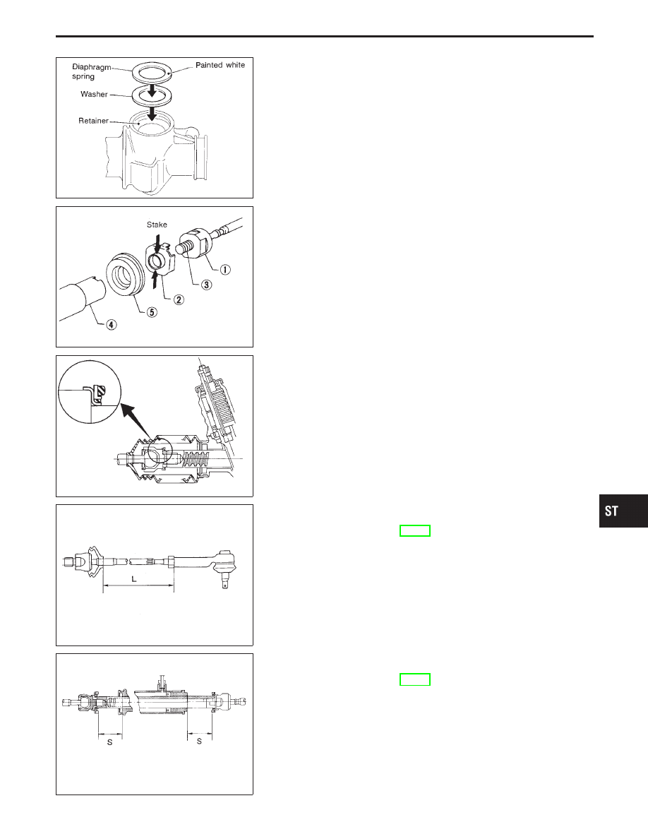
15. Install diaphragm spring at retainer.

I

Always install retainer, spring washer and diaphragm spring in
that order.

I

Make sure convex end (painted white) of diaphragm spring
faces outward when installing.

16. Install retainer spring and adjusting screw temporarily.

SST022C

CAUTION:

Ensure steering gear spacer is installed with rubber side fac-
ing rack.

I

Attach lock plate

q

2

to side rod inner socket

q

1

.

I

Insert steering gear spacer

q

5

to rack

q

4

.

I

Apply locking sealant to inner socket threads

q

3

.

Screw inner socket into rack

q

4

and tighten to specified torque.

I

Stake lock plate at two places.

SST328B

17. Install steering gear spacer

q

5

to lock plate

q

2

.

SST093B

18. Tighten outer socket lock nut.

Tie-rod length “L”:

Refer to SDS (ST-38).

SST307BA

19. Measure rack stroke.

Rack stroke “S”:

Refer to SDS (ST-38).

GI

MA

EM

LC

EC

FE

AT

PD

FA

RA

BR

RS

BT

HA

EL

IDX

POWER STEERING GEAR AND LINKAGE

Assembly (Cont’d)

ST-23

SST329B

20. Before installing boot, coat the contact surfaces between boot

and tie-rod with grease.

SST097B

21. Install boot clamps.

I

To install, wrap boot clamp around boot groove twice. To
tighten clamp, place a screwdriver through both rings. Twist
rings 4 to 4-1/2 turns while pulling with a force of approx. 98 N
(10 kg, 22 lb).

SST741C

I

Install boot clamp so that it is to the rear of the vehicle when
gear housing is attached to the body. (This will prevent inter-
ference with other parts.)

SST440A

I

Twist boot clamp in the direction shown in figure at left.

SST126B

I

After twisting boot clamp, bend twisted and diagonally so it
does not contact boot.

POWER STEERING GEAR AND LINKAGE

Assembly (Cont’d)

ST-24

SST742C

Adjustment

Adjust pinion rotating torque as follows:
1.

Set gears to Neutral without fluid in the gear.

2.

Coat the adjusting screw with locking sealant and screw it in.

3.

Lightly tighten lock nut.

4.

Tighten adjusting screw to a torque of 4.9 to 5.9 N

m (50 to 60

kg-cm, 43 to 52 in-lb).

5.

Loosen adjusting screw, then retighten it to 0.05 to 0.20 N

m

(0.5 to 2 kg-cm, 0.43 to 1.74 in-lb).

6.

Move rack over its entire stroke several times.

SST683C

7.

Measure pinion rotating torque within the range of 180° from
neutral position.
Stop the gear at the point of maximum torque.

8.

Loosen adjusting screw, then retighten it to 4.9 N

m (50 kg-cm,

43 in-lb).

9.

Loosen adjusting screw by 50° to 110°.

SST713C

10. Prevent adjusting screw from turning, and tighten lock nut to

specified torque.

SST090B

11. Check steering gear for rack sliding frictional force.

Around neutral point of rack stroke
±5.5 mm (±0.217 in):

122.6 - 166.7 N (12.5 - 17 kg, 27.6 - 37.5 lb)

Except for neutral point:

122.6 - 186.3 N (12.5 - 19 kg, 27.6 - 41.9 lb)

I

If sliding frictional force is out of specification, repeat the
adjustment procedure, starting from No. 4.

I

After the readjustment, if sliding force is still out of
specification, steering gear is damaged.

GI

MA

EM

LC

EC

FE

AT

PD

FA

RA

BR

RS

BT

HA

EL

IDX

POWER STEERING GEAR AND LINKAGE

ST-25

SST683C

12. Measure pinion rotating torque within the range of ±100° from

the neutral point.

Average rotating torque
[(Max. measured value + Min. measured value) x 0.5]:

0.8 - 1.3 N

m (8 - 13 kg-cm, 6.9 - 11.3 in-lb)

Maximum torque increment:

Less than 0.4 N

m (4 kg-cm, 3.5 in-lb)

Except for above mentioned measuring range:

Maximum rotating torque

1.9 N

m (19 kg-cm, 16 in-lb)

Maximum torque increment

Less than 0.6 N

m (6 kg-cm, 5.2 in-lb)

I

If pinion rotating torque is not within specification, readjust it.

I

After the readjustment, if pinion rotating torque is still out of
specification, steering gear is damaged.

SST090B

13. Check rack sliding force on vehicle as follows:
a.

Install steering gear onto vehicle, but do not connect tie-rod to
knuckle arm.

b.

Connect all piping and fill with steering fluid.

c.

Start engine and bleed air completely.

d.

Disconnect steering column lower joint from the gear.

e.

Keep engine at idle and make sure steering fluid has reached
normal operating temperature.

f.

Pull tie-rod slowly to move it from neutral position to ±11.5 mm
(±0.453 in) at speed of 3.5 mm (0.138 in)/s. Check that rack
sliding force is within specification.

Rack sliding force:

16 inch tire

235 - 294 N (24 - 30 kg, 53 - 66 lb)

17 inch tire

255 - 294 N (26 - 30 kg, 57 - 66 lb)

g.

Check sliding force outside above range.

Rack sliding force:

Not more than 294 N (30 kg, 66 lb)

I

If rack sliding force is not within specification, readjust by
repeating adjustment procedure from the beginning.

I

If rack sliding force is still out of specification after
readjustment, gear assembly needs to be replaced.

POWER STEERING GEAR AND LINKAGE

Adjustment (Cont’d)

ST-26


Content   ..  541  542  543  544   ..