Infiniti Q45 (FY33). Manual - part 387


  Index      Infiniti     Infiniti Q45 (FY33) - service repair manual 2001 year


Search            copyright infringement  


Content   ..  385  386  387  388   ..


Infiniti Q45 (FY33). Manual - part 387


SEL462W

6.

Touch “OK”.

7.

Carry out the next system setting or contact Communicator
Response Center and inform them that data has been updated
or IVCS unit has been replaced. For details, refer to EL-536.

NOTE: Whenever the phone number is updated or the IVCS

unit is replaced, the INFINITI Communicator system
automatically contacts the Communicator Response
Center the first time the vehicle is stared.

SEL466W

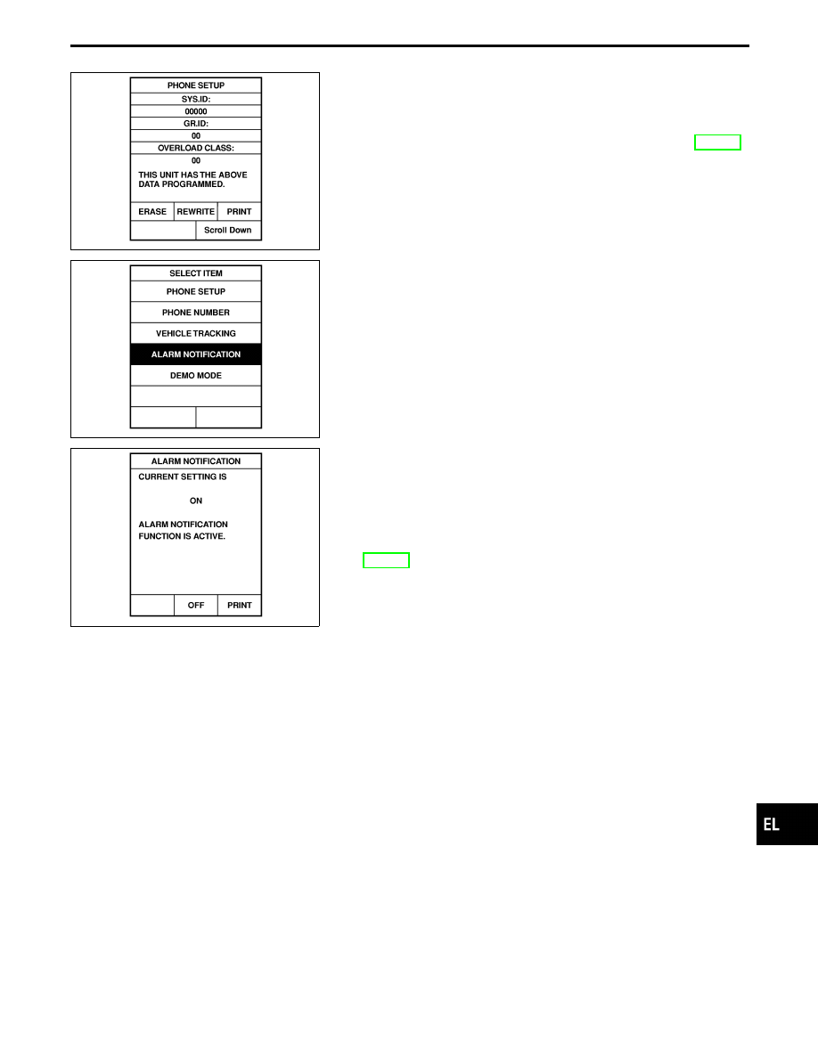
STOLEN VEHICLE TRACKING/ALARM NOTIFICATION
SETTING CHECK

1.

Touch “CONFIGURATION”.

2.

Touch “VEHICLE TRACKING” or “ALARM NOTIFICATION”.

SEL467W

3.

This function should always be “ON” (function activate.)

NOTE:

I

If either setting is “OFF”, contact the Communicator
Response Center at 1-888-427-4812 to verify the system
setting.

I

Whenever dialing the above number, information about
the vehicle is required by the operator. For details, refer to
EL-506.

GI

MA

EM

LC

EC

FE

AT

PD

FA

RA

BR

ST

RS

BT

HA

IDX

INFINITI COMMUNICATOR (IVCS)

System Setting (When IVCS unit is replaced)
(Cont’d)

EL-539

Precautions

WARNING:

Do not attempt to disassemble the monitor. Parts of the monitor have high voltages that can result in
severe and dangerous electric shock.

CAUTION:

I

Do not reverse battery connections.

I

Do not attach unauthorized parts.

I

Protect the unit from severe impact.

NOTE:
Before beginning repair, determine whether or not the unit is defective. Refer to “This Condition Is Not
Abnormal” (EL-578).

NAVIGATION SYSTEM

EL-540

SEL683V

System Description

OUTLINE

The Navigation System (Multi-AV System) relies upon three sens-
ing devices in order to determine vehicle location at regular time
intervals.
1.

Vehicle speed sensor: Determines the distance the vehicle has
traveled.

2.

Gyro (Angular velocity sensor): Determines vehicle steering
angle and directional change.

3.

GPS antenna (GPS data): Determines vehicle forward move-
ment and direction.

The data provided by the three sensing functions together with a
comparison of the mapping information read from the CD-ROM
drive permit accurate determination of the vehicle’s current location
and subsequent course (map matching). The information appears
on a liquid crystal display.
This comparison of GPS data (vehicle position sensing) and map
matching permits precise determination of vehicle location.

SEL684V

Position sensor operating principles

The sensor determines current vehicle location by calculating the
previously sensed position, the distance traveled from this position,
and the directional changes occurring during this travel.
1.

Distance traveled
The distance traveled is calculated using signals received from
the vehicle speed sensor. The sensor automatically compen-
sates for the slightly reduced wheel and tire diameter resulting
from tire wear.

2.

Forward movement (Direction)
Changes in the direction of forward movement are calculated
by the gyro (angular velocity sensor) and the GPS antenna
(GPS data). Each of these functions has its advantage and
disadvantages. Depending upon conditions, one function takes
precedence over the other to accurately determine the direc-
tion of forward movement.

Function type

Advantage

Disadvantage

Gyro (Angular
velocity sen-
sor)

I

Able to accurately detect
minute changes in steering
angle and direction.

I

Calculation errors may
accumulate over a long
period of continuous
vehicle travel.

GPS antenna
(GPS data)

I

Able to sense vehicle travel
in four general directions
(North, South, East, and
West)

I

Unable to detect direction
of vehicle travel at low
vehicle speeds.

GI

MA

EM

LC

EC

FE

AT

PD

FA

RA

BR

ST

RS

BT

HA

IDX

NAVIGATION SYSTEM

EL-541

SEL685V

Map matching

Map matching allows the driver to compare the sensed vehicle
location data with the road map contained in the CD-ROM drive.
Vehicle position is marked on the CD-ROM map. This permits the
driver to accurately determine his/her present position on the high-
way and to make appropriate course decisions.
When GPS data reception is poor during travel, the vehicle posi-
tion is not amended. At this time, manual manipulation of the CD-
ROM map position marker is required.

SEL686V

Map matching permits the driver to make priority judgments about
possible appropriate roads other than the one currently being trav-
eled.
If there is an error in the distance or direction of travel, there will
also be an error in the relative position of other routes. When two
routes are closely parallel to one another, the indicated position for
both routes will be nearly the same priority. This is so that, slight
changes in the steering direction may cause the marker to indicate
both routes alternately.

SEL687V

Newly constructed roads may not appear on the CD-ROM map. In
this case, map matching is not possible. Changes in the course of
a road will also prevent accurate map matching.
When driving on a road not shown on the CD-ROM map, the posi-
tion marker used for map matching may indicate a different route.
Even after returning to a route shown on the map, the position
marker may jump to the position currently detected.

SEL526V

GPS (Global Positioning System)

GPS is the global positioning system developed and operated by
the US Department of Defense. GPS satellites (NAVSTAR) trans-
mit radio waves and orbit around the earth at an altitude of approxi-
mately 21,000 km (13,000 miles).
GPS receiver calculates the three-dimensional position of the
vehicle (latitude, longitude, and altitude from the sea level) by the
time difference of the radio wave arriving from more than four GPS
satellites (three-dimensional positioning).
When the radio wave is received from only three GPS satellites, the
two-dimensional position (latitude and longitude) is calculated,
using the altitude from the sea level data calculated by using four
GPS satellites (two-dimensional positioning).

Positioning capability is degraded in the following cases.

I

In two-dimensional positioning, when the vehicle’s altitude
from the sea level changes, the precision becomes lower.

I

The location detection performance can have an error of about
100 m (300 ft) even in three-dimensional positioning with high
precision. Because the precision is influenced by the location
of GPS satellites used for positioning, the location detection
performance may drop depending on the location of GPS sat-
ellites.

NAVIGATION SYSTEM

System Description (Cont’d)

EL-542


Content   ..  385  386  387  388   ..