Infiniti Q45 (FY33). Manual - part 250


  Index      Infiniti     Infiniti Q45 (FY33) - service repair manual 2001 year


Search            copyright infringement  


Content   ..  248  249  250  251   ..


Infiniti Q45 (FY33). Manual - part 250


SEF757X

SEF451U

SEF166T

SEF663P

SEF452U

DIAGNOSTIC PROCEDURE

INSPECTION START

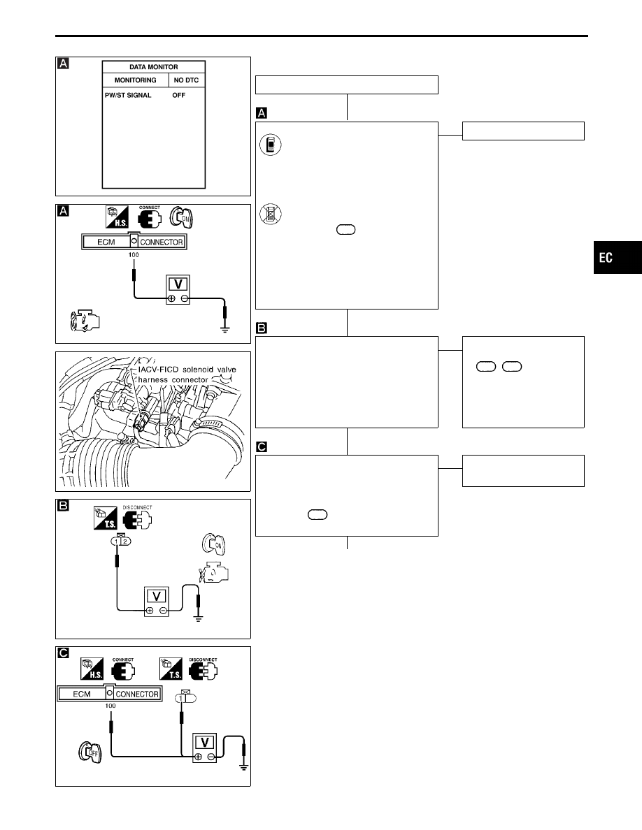
CHECK OVERALL FUNCTION.

1. Start engine.

2. Check “PW/ST SIGNAL” in

“DATA MONITOR” mode with
CONSULT-II.

Steering is neutral position: OFF
Steering is turned: ON

-------------------------------------------------------------------------------------------------------------------------------------- OR --------------------------------------------------------------------------------------------------------------------------------------

1. Start engine.

2. Check voltage between ECM

terminal

100

and ground under

the following conditions.
Voltage:

When steering wheel is
turned quickly.

Approximately 0V

Except above

Battery voltage

NG

E

OK

INSPECTION END

CHECK POWER SUPPLY-I.
1. Stop engine.
2. Disconnect IACV-FICD solenoid valve

harness connector.

3. Turn ignition switch “ON”.
4. Check voltage between terminal

q

1

and ground with CONSULT-II or tester.
Voltage: Battery voltage

OK

E

NG

Check the following.

I

Harness connectors

F63

,

M49

I

10A fuse

I

Harness for open or
short between IACV-
FICD solenoid valve and
fuse

CHECK POWER SUPPLY-II.
1. Turn ignition switch “OFF”.
2. Disconnect power steering oil pressure

switch harness connector.

3. Check voltage terminal

q

1

(or ECM

terminal

100

and ground.

Voltage: Battery voltage

OK

E

NG

Repair harness or connec-
tors.

q

A

(Go to next page.)

GI

MA

EM

LC

FE

AT

PD

FA

RA

BR

ST

RS

BT

HA

EL

IDX

TROUBLE DIAGNOSIS FOR NON-DETECTABLE ITEMS

Power Steering Oil Pressure Switch (Cont’d)

H

H

H

H

EC-529

SEF163T

SEF453U

q

A

CHECK GROUND CIRCUIT.
1. Turn ignition switch “OFF”.

2. Disconnect power steering oil pressure

switch harness connector.

3. Check harness continuity between ter-

minal

q

2

and engine ground.

Continuity should exist.
If OK, check harness for short to power.

OK

E

NG

Check the following.

I

Harness connectors

E101

,

E21

I

Harness for open or short
between power steering
pressure switch and
ground

If NG, repair open circuit or
short to power in harness
or connectors.

CHECK INPUT SIGNAL CIRCUIT.
1. Disconnect ECM harness connector.

2. Check harness continuity between ECM

terminal

100

and terminal

q

1

.

Continuity should exist.
If OK, check harness for short to ground
and short to power.

OK

E

NG

Repair harness or connec-
tors.

CHECK COMPONENTS
(Power steering oil pressure switch and
IACV-FICD solenoid valve).
Refer to “COMPONENT INSPECTION” on
next page.

OK

E

NG

Replace power steering oil
pressure switch or IACV-
FICD solenoid valve.

Perform “TROUBLE DIAGNOSIS FOR
INTERMITTENT INCIDENT”, EC-117.

INSPECTION END

TROUBLE DIAGNOSIS FOR NON-DETECTABLE ITEMS

Power Steering Oil Pressure Switch (Cont’d)

H

H

H

H

H

EC-530

SEF165T

COMPONENT INSPECTION

Power steering oil pressure switch

1.

Disconnect power steering oil pressure switch harness con-
nector then start engine.

2.

Check continuity between terminals

q

1

and

q

2

.

Conditions

Continuity

Steering wheel is being turned

Yes

Steering wheel is not being turned

No

If NG, replace power steering oil pressure switch.

SEF658Q

IACV-FICD solenoid valve

Disconnect IACV-FICD solenoid valve harness connector.

I

Check for clicking sound when applying 12V direct current to
terminals.

SEF097K

I

Check plunger for seizing or sticking.

I

Check for broken spring.

GI

MA

EM

LC

FE

AT

PD

FA

RA

BR

ST

RS

BT

HA

EL

IDX

TROUBLE DIAGNOSIS FOR NON-DETECTABLE ITEMS

Power Steering Oil Pressure Switch (Cont’d)

EC-531

Electrical Load Signal

TEC794

TROUBLE DIAGNOSIS FOR NON-DETECTABLE ITEMS

EC-532


Content   ..  248  249  250  251   ..