Infiniti Q45 (FY33). Manual - part 251


  Index      Infiniti     Infiniti Q45 (FY33) - service repair manual 2001 year


Search            copyright infringement  


Content   ..  249  250  251  252   ..


Infiniti Q45 (FY33). Manual - part 251


SEF454U

SEF455U

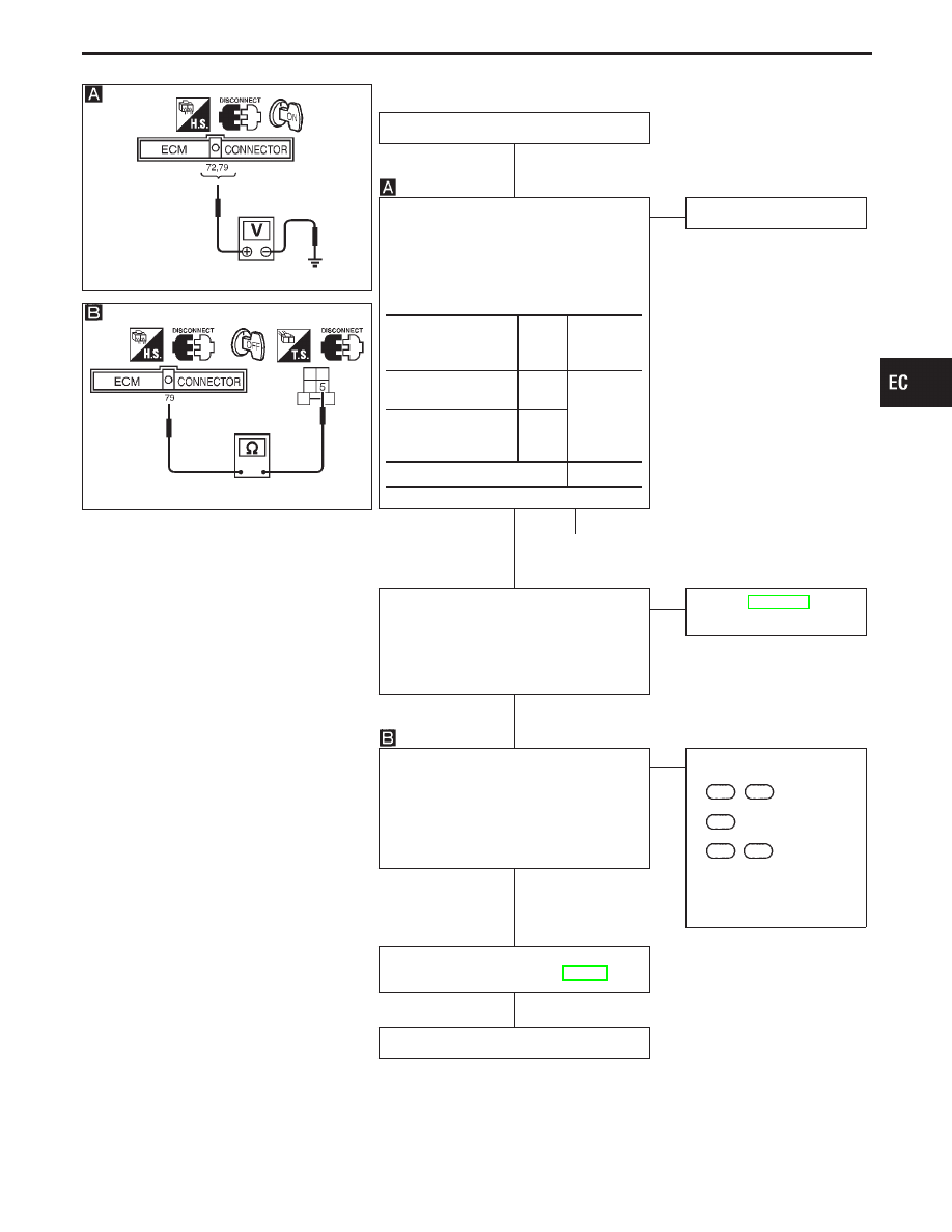
DIAGNOSTIC PROCEDURE

INSPECTION START

CHECK THE OVERALL FUNCTION.
1. Turn ignition switch “OFF”.
2. Disconnect ECM harness connector.
3. Turn ignition switch “ON”.
4. Check voltage between ECM terminal

q

72

,

q

79

and ground in the following con-

ditions.

NG(*1)

NG(*2)

E

OK

INSPECTION END

q

A

(Go to next page.)

CHECK REAR WINDOW DEFOGGER
FUNCTION.
1. Start engine.
2. Turn “ON” the rear defogger switch.
3. Check the rear windshield. Is the rear

windshield heated up?

OK

E

NG

Refer to EL section (RR
window defogger).

CHECK INPUT SIGNAL CIRCUIT FOR
RR/DEF.
Check harness continuity between ECM
terminal

q

79

and terminal

q

5

.

Continuity should exist.
If OK, check harness for short to ground
and short to power.

OK

E

NG

Check the following.

I

Harness connectors

F63

,

M49

I

Joint connector-10

M60

I

Harness connectors

M4

,

B3

If NG, repair open circuit or
short to ground or short to
power in harness or con-
nectors.

Perform “TROUBLE DIAGNOSIS FOR
INTERMITTENT INCIDENT”, EC-117.

INSPECTION END

Conditions

ECM

terminal

No.

Voltage (V)

Rear window defogger
switch “ON”*1

q

79

Battery volt-

age

Headlamp “ON” at 2nd
position with low
beam*2

q

72

Except the above*1

0

GI

MA

EM

LC

FE

AT

PD

FA

RA

BR

ST

RS

BT

HA

EL

IDX

TROUBLE DIAGNOSIS FOR NON-DETECTABLE ITEMS

Electrical Load Signal (Cont’d)

H

H

H

H

H

H

EC-533

SEF807W

q

A

CHECK HEADLAMP FUNCTION.
1. Start engine.
2. Turn the headlamp switch “ON” (2nd

position with low beam).

3. Check that headlamps are illuminated.

OK

E

NG

Refer to EL section
(HEADLAMP).

CHECK INPUT SIGNAL CIRCUIT FOR
HEADLAMP.
Check harness continuity between ECM
terminal

q

72

and terminal

q

6

(HEADLAMP

RELAY), or

q

7

(HID RELAY).

Continuity should exist.
If OK, check harness for short to ground
and short to power.

OK

E

NG

Check the following.

I

Harness connectors

F1

,

E14

If NG, repair open circuit or
short to ground or short to
power in harness or con-
nectors.

Perform “TROUBLE DIAGNOSIS FOR
INTERMITTENT INCIDENT”, EC-117.

INSPECTION END

TROUBLE DIAGNOSIS FOR NON-DETECTABLE ITEMS

Electrical Load Signal (Cont’d)

H

H

H

H

EC-534

MIL & Data Link Connectors

TEC080M

GI

MA

EM

LC

FE

AT

PD

FA

RA

BR

ST

RS

BT

HA

EL

IDX

TROUBLE DIAGNOSIS FOR NON-DETECTABLE ITEMS

EC-535

General Specifications

PRESSURE REGULATOR

Fuel pressure

kPa (kg/cm

2

, psi)

At idle

Approximately

235 (2.4, 34)

A few seconds after ignition
switch is turned OFF to ON

Approximately

294 (3.0, 43)

Inspection and Adjustment

Target idle speed*1

rpm

No-load*3

650±50

(in “P” or “N” position)

Base idle speed*2

rpm

No-load*3

600±50

(in “P” or “N” position)

Air conditioner: ON

(in “N” position)

More than 700 rpm

Ignition timing

15°±2° BTDC

*1: TPS harness connector connected.
*2: Using CONSULT-II “WORK SUPPORT” or TPS harness connector

disconnected.

*3: Under the following conditions:

I

Air conditioner switch: OFF

I

Electric load: OFF (Lights, heater, fan & rear defogger)

MASS AIR FLOW SENSOR

Supply voltage

V

Battery voltage (11 - 14)

Output voltage

V

1.0 - 1.7 at idle*

Approximately 2.1 at 2,500

Mass air flow
(Using CONSULT-II or GST)

g

m/sec

3.0 - 6.0 at idle*

12.9 - 25.3 at 2,500 rpm*

*: Engine is warmed up sufficiently and idling under no-load.

ENGINE COOLANT TEMPERATURE
SENSOR

Temperature °C (°F)

Resistance (k

)

20 (68)

2.1 - 2.9

50 (122)

0.68 - 1.00

90 (194)

0.236 - 0.260

EGR TEMPERATURE SENSOR

EGR temperature

°C (°F)

Voltage

(V)

Resistance

(M

)

0 (32)

4.61

0.68 - 1.11

50 (122)

2.53

0.09 - 0.12

100 (212)

0.87

0.017 - 0.024

HEATED OXYGEN SENSOR 1 HEATER
(FRONT)

Resistance [at 25°C (77°F)]

2.3 - 4.3

HEATED OXYGEN SENSOR 2 HEATER
(REAR)

Resistance [at 25°C (77°F)]

2.3 - 4.3

FUEL PUMP

Resistance [at 25°C (77°F)]

0.2 - 5.0

IACV-AAC VALVE (Step motor type)

Resistance [at 25°C (77°F)]

Approximately 30

INJECTOR

Resistance [at 25°C (77°F)]

10 - 14

THROTTLE POSITION SENSOR

Accelerator pedal conditions

Voltage*

Completely released (a)

0.15 - 0.85

Partially released

Between (a) and (b)

Completely depressed (b)

3.5 - 4.7

*: Measured with vacuum applied to the throttle opener using a

vacuum pump.

CALCULATED LOAD VALUE

Calculated load value %

(Using CONSULT-II or GST)

At idle

13.0 - 32

At 2,500 rpm

13.0 - 25.5

INTAKE AIR TEMPERATURE SENSOR

Temperature °C (°F)

Resistance

20 (68)

2.1 - 2.9 k

80 (176)

0.68 - 1.00 k

SERVICE DATA AND SPECIFICATIONS (SDS)

EC-536


Content   ..  249  250  251  252   ..