Infiniti Q45 (FY33). Manual - part 230
SEF353Q
SEC049C
SEF763P
SEF593U
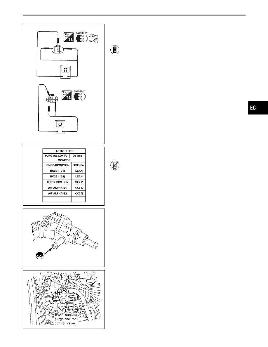
COMPONENT INSPECTION
EVAP canister purge volume control valve
1. Disconnect EVAP canister purge volume control valve
harness connector.
2. Check resistance between the following terminals.
terminal
q
2
and terminals
q
1
,
q
3
terminal
q
5
and terminals
q
4
,
q
6
Resistance:
Approximately 35 - 43
Ω
[At 25°C (77°F)]
3. Reconnect EVAP canister purge volume control valve
harness connector.
4. Remove EVAP canister purge volume control valve
from intake manifold collector and disconnect hoses
from the valve.
(Plug the purge hoses. The EVAP canister purge vol-
ume control valve harness connector should remain
connected.)
5. Turn ignition switch “ON”.
6. Perform “PURG VOL CONT/V” in “ACTIVE TEST”
mode with CONSULT-II. Check that EVAP canister
purge volume control valve shaft moves smoothly for-
ward and backward according to the valve opening.
If NG, replace the EVAP canister purge volume control
valve.
------------------------------------------------------------------------------------------------------------------------------------------------------------------------------------------------------------------------------------------------------ OR ------------------------------------------------------------------------------------------------------------------------------------------------------------------------------------------------------------------------------------------------------
1. Disconnect EVAP canister purge volume control valve
harness connector.
2. Check resistance between the following terminals.
terminal
q
2
and terminals
q
1
,
q
3
terminal
q
5
and terminals
q
4
,
q
6
Resistance:
Approximately 35 - 43
Ω
[At 25°C (77°F)]
3. Reconnect EVAP canister purge volume control valve
harness connector.
4. Remove EVAP canister purge volume control valve
from intake manifold collector and disconnect hoses
from the valve.
(Plug the purge hoses. The EVAP canister purge vol-
ume control valve harness connector should remain
connected.)
5. Turn ignition switch “ON” and “OFF”. Check that EVAP
canister purge volume control valve shaft moves
smoothly forward and backward according to the igni-
tion switch position.
If NG, replace the EVAP canister purge volume control
valve.
GI
MA
EM
LC
FE
AT
PD
FA
RA
BR
ST
RS
BT
HA
EL
IDX
TROUBLE DIAGNOSIS FOR DTC P1444
Evaporative Emission (EVAP) Canister Purge
Volume Control Valve (Cont’d)
EC-449