Infiniti Q45 (FY33). Manual - part 228
SEC050C
AEC783A
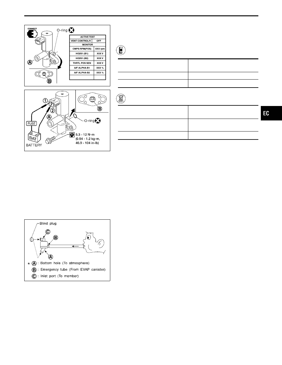
EVAP canister vent control valve
Check air passage continuity.
Perform “VENT CONTROL/V” in “ACTIVE TEST” mode with
CONSULT-II.
Condition
VENT CONTROL/V
Air passage continuity
between
q
A
and
q
B
ON
No
OFF
Yes
------------------------------------------------------------------------------------------------------------------------------------------------------------------------------------------------------------------------------------------------------ OR ------------------------------------------------------------------------------------------------------------------------------------------------------------------------------------------------------------------------------------------------------
Condition
Air passage continuity
between
q
A
and
q
B
12V direct current supply between ter-
minals
q
1
and
q
2
No
No supply
Yes
If NG or operation takes more than 1 second, clean valve using air
blower or replace as necessary.
If the portion
q
B
is rusted, replace EVAP canister vent control
valve.
Make sure new O-ring is installed properly.
SEF829T
Water separator
1.
Check visually for insect nests in the water separator air inlet.
2.
Check visually for cracks or flaws in the appearance.
3.
Check visually for cracks or flaws in the hose.
4.
Check that
q
A
and
q
C
are not clogged by blowing air into
q
B
with
q
A
, and then
q
C
plugged.
5.
In case of NG in items 2 - 4, replace the parts.
NOTE:
Do not disassemble water separator.
GI
MA
EM
LC
FE
AT
PD
FA
RA
BR
ST
RS
BT
HA
EL
IDX
TROUBLE DIAGNOSIS FOR DTC P1440
Evaporative Emission (EVAP) Control System
(Small Leak) (Positive Pressure) (Cont’d)
EC-441