Infiniti Q45 (FY33). Manual - part 229


  Index      Infiniti     Infiniti Q45 (FY33) - service repair manual 2001 year


Search            copyright infringement  


Content   ..  227  228  229  230   ..


Infiniti Q45 (FY33). Manual - part 229


CONSULT-II REFERENCE VALUE IN DATA MONITOR MODE

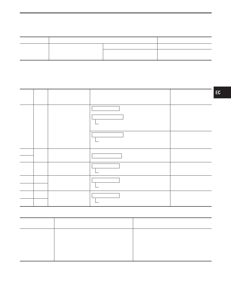
Specification data are reference values.

MONITOR ITEM

CONDITION

SPECIFICATION

PURG VOL C/V

I

Engine: After warming up

I

Air conditioner switch “OFF”

Idle

0 step

Vehicle running
(Shift lever “1”)

ECM TERMINALS AND REFERENCE VALUE

Specification data are reference values and are measured between each terminal and ground.

CAUTION:

Do not use ECM ground terminals when measuring voltage. Doing so may result in damage to the
ECM’s transistor. Use a ground other than ECM terminals such as the body ground.

TER-

MINAL

NO.

WIRE

COLOR

ITEM

CONDITION

DATA

(DC Voltage)

124

W/B

ECM relay (Self-shutoff)

Engine is running.

Ignition switch “OFF”

For a few seconds after turning ignition switch
“OFF”

0 - 1V

Ignition switch “OFF”

A few seconds passed after turning ignition
switch “OFF”

BATTERY VOLTAGE
(11 - 14V)

130

R/G

Power supply for ECM

Ignition switch “ON”

BATTERY VOLTAGE
(11 - 14V)

131

123

W/L

Current return

Engine is running.

Idle speed

BATTERY VOLTAGE
(11 - 14V)

28

BR/Y

EVAP canister purge vol-
ume control valve

Engine is running.

Idle speed

0 - 0.4V or
BATTERY VOLTAGE
(11 - 14V)

29

G

35

G/OR

EVAP canister purge vol-
ume control valve

Engine is running.

Idle speed

0 - 0.4V or
BATTERY VOLTAGE
(11 - 14V)

36

L/B

ON BOARD DIAGNOSIS LOGIC

Diagnostic Trouble

Code No.

Malfunction is detected when ....

Check Items

(Possible Cause)

P1444
0214

I

The canister purge flow is detected during the
specified driving conditions, even when EVAP can-
ister purge volume control valve is completely
closed.

I

EVAP control system pressure sensor

I

EVAP canister purge volume control valve (The
valve is stuck open.)

I

EVAP canister purge control valve

I

Hoses
(Hoses are connected incorrectly or clogged.)

I

EVAP canister vent control valve

GI

MA

EM

LC

FE

AT

PD

FA

RA

BR

ST

RS

BT

HA

EL

IDX

TROUBLE DIAGNOSIS FOR DTC P1444

Evaporative Emission (EVAP) Canister Purge
Volume Control Valve (Cont’d)

EC-445

SEF809X

SEF811X

SEF810X

SEF812X

DIAGNOSTIC TROUBLE CODE CONFIRMATION
PROCEDURE

CAUTION:

Always drive vehicle at a safe speed.
NOTE:

I

If “DIAGNOSTIC TROUBLE CODE CONFIRMATION PRO-
CEDURE” has been previously conducted, always turn
ignition switch “OFF” and wait at least 5 seconds before
conducting the next test.

TESTING CONDITION:
Always perform test at temperature above 0°C (32°F).

1) Start engine and warm it up to normal operating tem-

perature.

2) Turn ignition switch “OFF” and wait at least 5 seconds.
3) Turn ignition switch “ON”.
4) Select “PURG CN/V & S/V P1493” of “EVAPORATIVE

SYSTEM” in “DTC WORK SUPPORT” mode with CON-
SULT-II.

5) Touch “START”.
6) Start engine (TCS switch “OFF”) and let it idle for at

least 90 seconds.

7) When the following conditions are met, “TESTING” will

be displayed on the CONSULT-II screen. Maintain the
conditions continuously until “TESTING” changes to
“COMPLETED”. (It will take for at least 30 seconds.)
Selector lever: Suitable position
Vehicle speed: 36 - 120 km/h (22 - 75 MPH)
CMPS-RPM (POS): 900 - 6,300 rpm
B/FUEL SCHDL: 2 - 4.8 msec

8) Stop vehicle with engine running.
9) Select “PURG VOL C/V P1444” of “EVAPORATIVE

SYSTEM” in “DTC WORK SUPPORT” mode with CON-
SULT-II.

10) Touch “START”.
If “COMPLETED” is displayed, go to step 12).
11) When the following conditions are met, “TESTING” will

be displayed on the CONSULT-II screen. Maintain the
conditions continuously until “TESTING” changes to
“COMPLETED”. (It will take for at least 20 seconds.)
Selector lever: Suitable position
Vehicle speed: 36 - 120 km/h (22 - 75 MPH)
CMPS-RPM (POS): 900 - 6,300 rpm
B/FUEL SCHDL: 2 - 4.8 msec

If “TESTING” is not displayed after 5 minutes, retry
from step 2).
12) Make sure that “OK” is displayed after touching “SELF-

DIAG RESULTS”. If “NG” is displayed, refer to “DIAG-
NOSTIC PROCEDURE”, EC-448.

TROUBLE DIAGNOSIS FOR DTC P1444

Evaporative Emission (EVAP) Canister Purge
Volume Control Valve (Cont’d)

EC-446

SEF519R

SEF615U

------------------------------------------------------------------------------------------------------------------------------------------------------------------------------------------------------------------------------------------------------ OR ------------------------------------------------------------------------------------------------------------------------------------------------------------------------------------------------------------------------------------------------------

1) Start engine (TCS switch “OFF”) and warm it up to nor-

mal operating temperature.

2) Select “MODE 1” with GST.
3) Check coolant temperature.

Coolant temperature: 40 - 100°C (104 - 212°F)
Be sure that water temperature does not exceed 100°C
(212°F). If it becomes higher than 100°C (212°F), cool
down the engine and perform the procedure again from
the beginning.

4) Turn ignition switch “OFF” and wait at least 5 seconds.
5) Turn ignition switch “ON” and wait at least 15 seconds.
6) Restart engine and let it idle for at least 80 seconds.
7) Maintain the following conditions for at least 80 sec-

onds.
Gear position : Suitable gear position
Vehicle speed: 36 - 120 km/h (22 - 75 MPH)
CMPS-RPM (POS) : 900 - 6,300 rpm
Coolant temperature: 40 - 100°C (104 - 212°F)

8) Select “MODE 7” with GST.
9) If 1st trip DTC is detected, go to “DIAGNOSTIC

PROCEDURE”, EC-448.

NOTE:

I

Hold the accelerator pedal as steady as possible during
driving in steps 7.

I

If the driving conditions are not satisfied in steps 7, restart
the procedure.

I

It is better that the fuel level is low.

------------------------------------------------------------------------------------------------------------------------------------------------------------------------------------------------------------------------------------------------------ OR ------------------------------------------------------------------------------------------------------------------------------------------------------------------------------------------------------------------------------------------------------

1) Start engine (TCS switch “OFF”) and warm it up to nor-

mal operating temperature.

2) Check voltage between ECM terminal

q

67

and ground

Voltage: 0.8 - 1.5V
Perform the following procedure before the voltage
drops below 0.8V. If the voltage drops below 0.8V, cool
down the engine and perform the entire procedure all
over again.

3) Turn ignition switch “OFF” and wait at least 5 seconds.
4) Turn ignition switch “ON” and wait at least 15 seconds.
5) Restart engine and let it idle for at least 80 seconds.
6) Maintain the following conditions for at least 80 sec-

onds.
Gear position : Suitable gear position
Vehicle speed: 36 - 120 km/h (22 - 75 MPH)
CMPS-RPM : 900 - 6,300 rpm
Check voltage between ECM terminal

q

67

and

ground: 0.8 - 1.5V

7) Turn ignition switch “OFF”, wait at least 5 seconds, and

then turn “ON”.

8) Perform “Diagnostic Test Mode II (Self-diagnostic

results)” with ECM.

9) If 1st trip DTC is detected, go to “DIAGNOSTIC

PROCEDURE”, EC-448.

NOTE:

I

Hold the accelerator pedal as steady as possible during
driving in steps 6.

I

If the driving conditions are not satisfied in steps 6, restart
the procedure.

I

It is better that the fuel level is low.

GI

MA

EM

LC

FE

AT

PD

FA

RA

BR

ST

RS

BT

HA

EL

IDX

TROUBLE DIAGNOSIS FOR DTC P1444

Evaporative Emission (EVAP) Canister Purge
Volume Control Valve (Cont’d)

EC-447

SEF417U

SEF427U

SEF596U

DIAGNOSTIC PROCEDURE

INSPECTION START

CHECK COMPONENT
(EVAP canister purge volume control
valve).
Refer to “COMPONENT INSPECTION” on
next page.

OK

E

NG

Replace EVAP canister
purge volume control
valve.

CHECK COMPONENT
(EVAP control system pressure sensor).
1. Check disconnection of hose connected

to the sensor.

2. Check sensor harness connector for

water.
Water should not exist.
If OK, go to step 3.

3. Check EVAP control system pressure

sensor.

Refer to “COMPONENT INSPECTION”,
EC-450.

OK

E

NG

Replace EVAP control sys-
tem pressure sensor and
repair or replace harness
and connector.

CHECK COMPONENT
(EVAP canister vent control valve).
Refer to “COMPONENT INSPECTION”,
EC-450.

OK

E

NG

Replace EVAP canister
vent control valve.

CHECK RUBBER TUBE FOR CLOG-
GING.
Check obstructed water separator,
improper connection of hose and rubber
tube to EVAP canister vent control valve
and clean the rubber tube using air
blower.
For water separator, refer to “COMPO-
NENT INSPECTION”, EC-455.

OK

E

NG

Clean, repair or replace
rubber tube and/or water
separator.

CHECK IF EVAP CANISTER IS SATU-
RATED WITH WATER.
1. Remove EVAP canister with EVAP can-

ister vent control valve attached.

2. Check if water will drain from the EVAP

canister. If it will, weigh the EVAP canis-
ter with the vent control valve attached.
If the weight is:

More than 1.8 kg (4.0 lb)

NG

Less than 1.8 kg (4.0 lb)

OK

OK

E

NG

Replace EVAP canister
and check the following.
1. Check hose connections

to the EVAP canister
and water separator for
clogging and poor con-
nection.

2. Check water separator.

Refer to “COMPONENT
INSPECTION”, EC-441.

Perform “TROUBLE DIAGNOSIS FOR
INTERMITTENT INCIDENT”, EC-117.

INSPECTION END

TROUBLE DIAGNOSIS FOR DTC P1444

Evaporative Emission (EVAP) Canister Purge
Volume Control Valve (Cont’d)

H

H

H

H

H

H

H

EC-448


Content   ..  227  228  229  230   ..