Infiniti Q45 (FY33). Manual - part 207
DIAGNOSTIC PROCEDURE
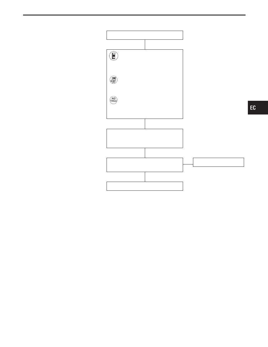
INSPECTION START
1) Turn ignition switch “ON”.
2) Select “SELF-DIAG RESULTS”
mode with CONSULT-II.
3) Touch “ERASE”.
-------------------------------------------------------------------------------------------------------------------------------------- OR --------------------------------------------------------------------------------------------------------------------------------------
1) Turn ignition switch “ON”.
2) Select MODE 4 with GST.
3) Touch “ERASE”.
-------------------------------------------------------------------------------------------------------------------------------------- OR --------------------------------------------------------------------------------------------------------------------------------------
1) Turn ignition switch “ON”.
2) Erase the Diagnostic Test Mode
II (Self-diagnostic results)
memory.
PERFORM DIAGNOSTIC TROUBLE
CODE CONFIRMATION PROCEDURE.
See previous page.
Is the DTC P0605 (0301) displayed
again?
No
E
Yes
Replace ECM.
INSPECTION END
GI
MA
EM
LC
FE
AT
PD
FA
RA
BR
ST
RS
BT
HA
EL
IDX
TROUBLE DIAGNOSIS FOR DTC P0605
Engine Control Module (ECM) (Cont’d)
H
H
H
H
EC-357