Infiniti Q45 (FY33). Manual - part 195


  Index      Infiniti     Infiniti Q45 (FY33) - service repair manual 2001 year


Search            copyright infringement  


Content   ..  193  194  195  196   ..


Infiniti Q45 (FY33). Manual - part 195


Evaporative Emission (EVAP) Canister Purge
Volume Control Valve (Circuit)

SYSTEM DESCRIPTION

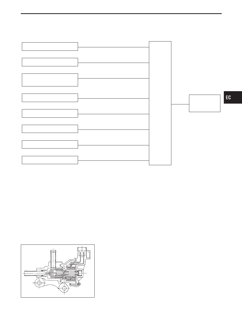
Camshaft position sensor

E

Engine speed

ECM

E

EVAP canister
purge volume
control valve

Mass air flow sensor

E

Amount of intake air

Engine coolant temperature sen-
sor

E

Engine coolant temperature

Ignition switch

E

Start signal

Throttle position sensor

E

Throttle position

Heated oxygen sensor 1 (front)

E

Density of oxygen in exhaust gas

(Mixture ratio feedback signal)

Fuel tank temperature sensor

E

Fuel temperature in fuel tank

Vehicle speed sensor

E

Vehicle speed

This system controls flow rate of fuel vapor from the EVAP canister. The opening of the vapor by-pass pas-
sage in the EVAP canister purge volume control valve changes to control the flow rate. A built-in step motor
moves the valve in steps corresponding to the ECM output pulses. The opening of the valve varies for opti-
mum engine control. The optimum value stored in the ECM is determined by considering various engine con-
ditions. When the engine is operating, the flow rate of fuel vapor from the EVAP canister is regulated as the
air flow changes.

SEF249P

COMPONENT DESCRIPTION

The EVAP canister purge volume control valve uses a step motor
to control the flow rate of fuel vapor from the EVAP canister. This
motor has four winding phases. It operates according to the output
pulse signal of the ECM. Two windings are turned ON and OFF in
sequence. Each time an ON pulse is issued, the valve opens or
closes, changing the flow rate. When no change in the flow rate is
needed, the ECM does not issue the pulse signal. A certain volt-
age signal is issued so that the valve remains at that particular
opening.

GI

MA

EM

LC

FE

AT

PD

FA

RA

BR

ST

RS

BT

HA

EL

IDX

TROUBLE DIAGNOSIS FOR DTC P0443

EC-309

CONSULT-II REFERENCE VALUE IN DATA MONITOR MODE

Specification data are reference values.

MONITOR ITEM

CONDITION

SPECIFICATION

PURG VOL C/V

I

Engine: After warming up

I

Air conditioner switch “OFF”

Idle

0 step

Vehicle running
(Shift lever “1”)

ECM TERMINALS AND REFERENCE VALUE

Specification data are reference values and are measured between each terminal and ground.

CAUTION:

Do not use ECM ground terminals when measuring voltage. Doing so may result in damage to the
ECM’s transistor. Use a ground other than ECM terminals such as the body ground.

TER-

MINAL

NO.

WIRE

COLOR

ITEM

CONDITION

DATA

(DC Voltage)

124

W/B

ECM relay (Self-shutoff)

Engine is running.

Ignition switch “OFF”

For a few seconds after turning ignition switch
“OFF”

0 - 1V

Ignition switch “OFF”

A few seconds passed after turning ignition
switch “OFF”

BATTERY VOLTAGE
(11 - 14V)

130

R/G

Power supply for ECM

Ignition switch “ON”

BATTERY VOLTAGE
(11 - 14V)

131

123

W/L

Current return

Engine is running.

Idle speed

BATTERY VOLTAGE
(11 - 14V)

28

BR/Y

EVAP canister purge vol-
ume control valve

Engine is running.

Idle speed

0 - 0.4V or
BATTERY VOLTAGE
(11 - 14V)

29

G

35

G/OR

EVAP canister purge vol-
ume control valve

Engine is running.

Idle speed

0 - 0.4V or
BATTERY VOLTAGE
(11 - 14V)

36

L/B

ON BOARD DIAGNOSIS LOGIC

Diagnostic Trouble

Code No.

Malfunction is detected when ....

Check Items

(Possible Cause)

P0443
1008

I

An improper voltage signal is sent to ECM through
the valve.

I

Harness or connectors
(The valve circuit is open or shorted.)

I

EVAP canister purge volume control valve

TROUBLE DIAGNOSIS FOR DTC P0443

Evaporative Emission (EVAP) Canister Purge
Volume Control Valve (Circuit) (Cont’d)

EC-310

SEF272Y

DIAGNOSTIC TROUBLE CODE CONFIRMATION
PROCEDURE

NOTE:
If “DIAGNOSTIC TROUBLE CODE CONFIRMATION PROCE-
DURE” has been previously conducted, always turn ignition
switch “OFF” and wait at least 5 seconds before conducting
the next test.
TESTING CONDITION:
Before performing the following procedure, confirm that bat-
tery voltage is more than 11V at ignition switch “ON”.

1) Turn ignition switch “ON”.
2) Select “DATA MONITOR” mode with CONSULT-II.
3) Wait at least 5 seconds.
4) If 1st trip DTC is detected, go to “DIAGNOSTIC

PROCEDURE”, EC-313.

------------------------------------------------------------------------------------------------------------------------------------------------------------------------------------------------------------------------------------------------------ OR ------------------------------------------------------------------------------------------------------------------------------------------------------------------------------------------------------------------------------------------------------

Follow the procedure “With CONSULT-II” above.

GI

MA

EM

LC

FE

AT

PD

FA

RA

BR

ST

RS

BT

HA

EL

IDX

TROUBLE DIAGNOSIS FOR DTC P0443

Evaporative Emission (EVAP) Canister Purge
Volume Control Valve (Circuit) (Cont’d)

EC-311

TEC823

TROUBLE DIAGNOSIS FOR DTC P0443

Evaporative Emission (EVAP) Canister Purge
Volume Control Valve (Circuit) (Cont’d)

EC-312


Content   ..  193  194  195  196   ..