Infiniti Q45 (FY33). Manual - part 196
SEF417U
SEF578Q
SEF418U
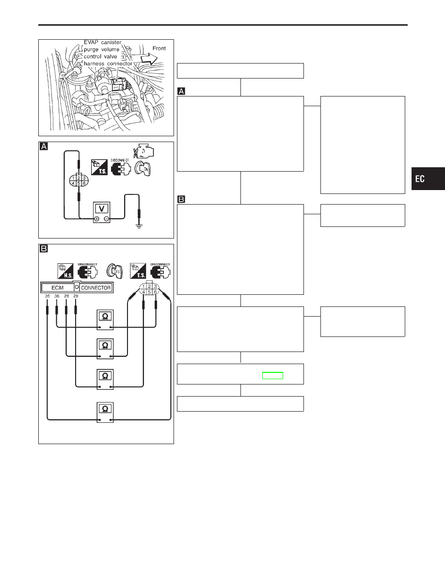
DIAGNOSTIC PROCEDURE
INSPECTION START
CHECK POWER SUPPLY.
1. Turn ignition switch “OFF”.
2. Disconnect EVAP canister purge vol-
ume control valve harness connector.
3. Turn ignition switch “ON”.
4. Check voltage between terminals
q
2
,
q
5
and engine ground with CONSULT-II
or tester.
Voltage: Battery voltage
OK
E
NG
Check the following.
I
Harness for open or
short between EVAP
canister purge volume
control valve and ECM
relay
I
Harness for open or
short between EVAP
canister purge volume
control valve and ECM
If NG, repair harness or
connectors.
CHECK OUTPUT SIGNAL CIRCUIT.
1. Turn ignition switch “OFF”.
2. Disconnect ECM harness connector.
3. Check harness continuity between
ECM terminal
q
28
and terminal
q
1
,
ECM terminal
q
29
and terminal
q
4
,
ECM terminal
q
35
and terminal
q
3
,
ECM terminal
q
36
and terminal
q
6
.
Continuity should exist.
If OK, check harness for short to
ground and short to power.
OK
E
NG
Replace harness or con-
nectors.
CHECK COMPONENT
(EVAP canister purge volume control
valve).
Refer to “COMPONENT INSPECTION” on
next page.
OK
E
NG
Replace EVAP canister
purge volume control
valve.
Perform “TROUBLE DIAGNOSIS FOR
INTERMITTENT INCIDENT”, EC-117.
INSPECTION END
GI
MA
EM
LC
FE
AT
PD
FA
RA
BR
ST
RS
BT
HA
EL
IDX
TROUBLE DIAGNOSIS FOR DTC P0443
Evaporative Emission (EVAP) Canister Purge
Volume Control Valve (Circuit) (Cont’d)
H
H
H
H
H
EC-313