Infiniti Q45 (FY33). Manual - part 179


  Index      Infiniti     Infiniti Q45 (FY33) - service repair manual 2001 year


Search            copyright infringement  


Content   ..  177  178  179  180   ..


Infiniti Q45 (FY33). Manual - part 179


Fuel Injection System Function (Lean side)
(P0171: Bank 1), (P0174: Bank 2)

ON BOARD DIAGNOSIS LOGIC

With the Air/Fuel Mixture Ratio Self-Learning Control, the actual mixture ratio can be brought closely to the
theoretical mixture ratio based on the mixture ratio feedback signal from the heated oxygen sensor 1 (front).
The ECM calculates the necessary compensation to correct the offset between the actual and the theoretical
ratios.
In case the amount of the compensation value is extremely large (The actual mixture ratio is too lean.), the
ECM judges the condition as the fuel injection system malfunction and light up the MIL (2 trip detection logic).

Heated oxygen sensor 1 (front)

E

Density of oxygen in exhaust gas

(Mixture ratio feedback signal)

ECM

E

Injectors

Diagnostic Trouble

Code No.

Malfunction is detected when ...

Check Items

(Possible Cause)

P0171
0115
(Bank 1)

I

Fuel injection system does not operate properly.

I

The amount of mixture ratio compensation is too large. (The
mixture ratio is too lean.)

I

Intake air leaks

I

Heated oxygen sensor 1 (front)

I

Injectors

I

Exhaust gas leaks

I

Incorrect fuel pressure

I

Lack of fuel

I

Mass air flow sensor

P0174
0210
(Bank 2)

SEF985Z

SEC042C

DIAGNOSTIC TROUBLE CODE CONFIRMATION
PROCEDURE

NOTE:
If “DIAGNOSTIC TROUBLE CODE CONFIRMATION PROCE-
DURE” has been previously conducted, always turn ignition
switch “OFF” and wait at least 5 seconds before conducting
the next test.

1) Start engine and warm it up to normal operating tem-

perature.

2) Turn ignition switch “OFF” and wait at least 5 seconds.
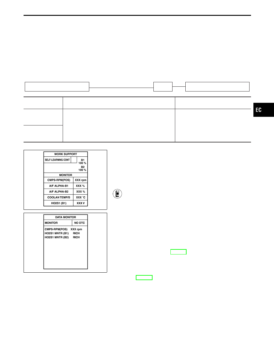
3) Turn ignition switch “ON” and select “SELF-LEARN

CONTROL” in “WORK SUPPORT” mode with CON-
SULT-II.

4) Clear the self-learning control coefficient by touching

“CLEAR”.

5) Select “DATA MONITOR” mode with CONSULT-II.
6) Start engine again and let it idle for at least 10 minutes.

The 1st trip DTC P0171 should be detected at this
stage, if a malfunction exists. If so, go to “DIAGNOSTIC
PROCEDURE”, EC-249.

7) If it is difficult to start engine at step 6), the fuel injec-

tion system has a malfunction.

8) Crank engine while depressing accelerator pedal. If

engine starts, go to “DIAGNOSTIC PROCEDURE”,
EC-249. If engine does not start, visually check for
exhaust and intake air leak.

------------------------------------------------------------------------------------------------------------------------------------------------------------------------------------------------------------------------------------------------------ OR ------------------------------------------------------------------------------------------------------------------------------------------------------------------------------------------------------------------------------------------------------

GI

MA

EM

LC

FE

AT

PD

FA

RA

BR

ST

RS

BT

HA

EL

IDX

TROUBLE DIAGNOSIS FOR DTC P0171 (B1), P0174 (B2)

EC-245

SEF395W

1) Start engine and warm it up to normal operating tem-

perature.

2) Turn ignition switch “OFF” and wait at least 5 seconds.
3) Disconnect mass air flow sensor harness connector.

Then restart and run engine for at least 3 seconds at
idle speed.

4) Stop engine and reconnect mass air flow sensor har-

ness connector.

5) Select “MODE 7” with GST. Make sure 1st trip DTC

P0100 is detected.

6) Select “MODE 4” with GST and erase the 1st trip DTC

P0100.

7) Start engine again and run it for at least 10 minutes at

idle speed.

8) Select “MODE 7” with GST. The 1st trip DTC P0171

should be detected at this stage, if a malfunction exists.
If so, go to “DIAGNOSTIC PROCEDURE”, EC-249.

9) If it is difficult to start engine at step 8, the fuel injection

system has a malfunction.

10) Crank engine while depressing accelerator pedal.

If engine starts, go to “DIAGNOSTIC PROCEDURE”,
EC-249.
If the engine does not start, visually check for exhaust
and intake air leak.

------------------------------------------------------------------------------------------------------------------------------------------------------------------------------------------------------------------------------------------------------ OR ------------------------------------------------------------------------------------------------------------------------------------------------------------------------------------------------------------------------------------------------------

1) Start engine and warm it up to normal operating tem-

perature.

2) Turn ignition switch “OFF” and wait at least 5 seconds.
3) Disconnect mass air flow sensor harness connector.

Then restart engine and run it at least 3 seconds at idle
speed.

4) Stop engine and reconnect mass air flow sensor har-

ness connector.

5) Turn ignition switch “ON”.
6) Perform “Diagnostic Test Mode II (Self-diagnostic

results)” with ECM. Make sure DTC 0102 is detected.

7) Erase the DTC 0102 by changing from Diagnostic Test

Mode II to Diagnostic Test Mode I.

8) Perform “Diagnostic Test Mode II (Self-diagnostic

results)” with ECM. Make sure DTC 0505 is detected.

9) Start engine again and run it for at least 10 minutes at

idle speed.
The DTC 0115 should be detected at this stage, if a
malfunction

exists.

If

so,

go

to

“DIAGNOSTIC

PROCEDURE”, EC-249.

10) If it is difficult to start engine at step 9, the fuel injection

system also has a malfunction.

11) Crank engine while depressing accelerator pedal.

If engine starts, go to “DIAGNOSTIC PROCEDURE”,
EC-249.
If the engine does not start, visually check for exhaust
and intake air leak.

TROUBLE DIAGNOSIS FOR DTC P0171 (B1), P0174 (B2)

Fuel Injection System Function (Lean side)
(P0171: Bank 1), (P0174: Bank 2) (Cont’d)

EC-246

BANK 1

TEC791

GI

MA

EM

LC

FE

AT

PD

FA

RA

BR

ST

RS

BT

HA

EL

IDX

TROUBLE DIAGNOSIS FOR DTC P0171 (B1), P0174 (B2)

Fuel Injection System Function (Lean side)
(P0171: Bank 1), (P0174: Bank 2) (Cont’d)

EC-247

BANK 2

TEC793

TROUBLE DIAGNOSIS FOR DTC P0171 (B1), P0174 (B2)

Fuel Injection System Function (Lean side)
(P0171: Bank 1), (P0174: Bank 2) (Cont’d)

EC-248


Content   ..  177  178  179  180   ..