Infiniti Q45 (FY33). Manual - part 180
SEF099P
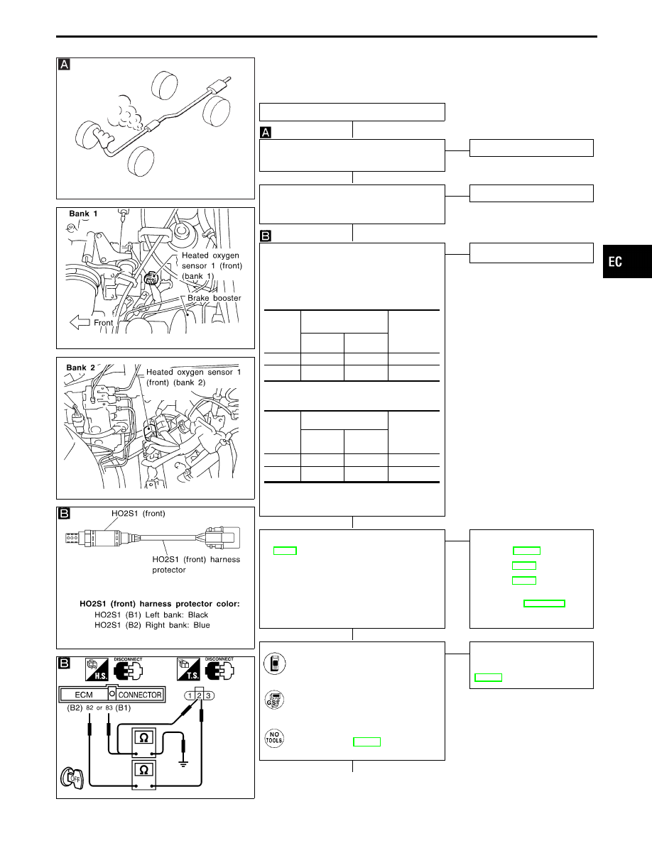
SEF054TI
SEF056TH
SEF409WA
SEF390UA
DIAGNOSTIC PROCEDURE
INSPECTION START
CHECK EXHAUST AIR LEAK.
Start engine and run it at idle. Listen for an
exhaust air leak before three way catalyst.
OK
E
NG
Repair or replace.
CHECK FOR INTAKE AIR LEAK.
Start engine and run it at idle. Listen for an
intake air leak between the mass air flow sensor
and the intake manifold.
OK
E
NG
Repair or replace.
CHECK HEATED OXYGEN SENSOR 1
(FRONT).
1. Turn ignition switch “OFF”.
2. Disconnect heated oxygen sensor 1 (front)
harness connector and ECM harness connec-
tor.
3. Check harness continuity between ECM and
sensor terminals.
Continuity should exist.
4. Check harness continuity between ECM and
sensor or ground.
Continuity should not exist.
If OK, check harness for short to ground and
short to power.
OK
E
NG
Repair harness or connectors.
CHECK FUEL PRESSURE.
1. Release fuel pressure to zero. Refer to
2. Install fuel pressure gauge and check fuel
pressure.
At idle:
Approx. 235 kPa
(2.4 kg/cm
2
, 34 psi)
A few seconds after ignition switch is
turned OFF to ON:
Approx. 294 kPa
(3.0 kg/cm
2
, 43 psi)
OK
E
NG
Check the following.
I
Fuel pump and circuit
Refer to EC-523.
I
Fuel pressure regulator
Refer to EC-37.
I
Fuel lines
Refer to EC-38.
I
Fuel lines
Refer to “ENGINE MAINTE-
NANCE” in MA section.
I
Fuel filter for clogging
If NG, repair or replace.
CHECK MASS AIR FLOW SENSOR.
Check “MASS AIR FLOW” in “DATA
MONITOR” mode with CONSULT-II.
3.0 - 6.0 g
⋅
m/sec: at idling
12.9 - 25.3 g
⋅
m/sec: at 2,500 rpm
---------------------------------------------------------------------------------------------------------------------------------------- OR ----------------------------------------------------------------------------------------------------------------------------------------
Check “mass air flow” in MODE 1 with
GST.
3.0 - 6.0 g
⋅
m/sec: at idling
12.9 - 25.3 g
⋅
m/sec: at 2,500 rpm
---------------------------------------------------------------------------------------------------------------------------------------- OR ----------------------------------------------------------------------------------------------------------------------------------------
Check mass air flow sensor output
voltage, refer to EC-131.
Approximately 2.1V: at 2,500 rpm
OK
E
NG
Check connectors for rusted
terminals or loose connections
in the mass air flow sensor cir-
cuit or engine grounds. Refer to
EC-124.
q
A
(Go to next page.)
DTC
Terminals
Bank
(Harness
protector
color)
ECM
Sensor
P0171
83
2
(B1) (Black)
P0174
82
2
(B2) (Blue)
DTC
Terminals
Bank
(Harness
protector
color)
ECM or
sensor
Ground
P0171
83 or 2
Ground
(B1) (Black)
P0174
82 or 2
Ground
(B2) (Blue)
GI
MA
EM
LC
FE
AT
PD
FA
RA
BR
ST
RS
BT
HA
EL
IDX
TROUBLE DIAGNOSIS FOR DTC P0171 (B1), P0174 (B2)
Fuel Injection System Function (Lean side)
(P0171: Bank 1), (P0174: Bank 2) (Cont’d)
H
H
H
H
H
H
EC-249