Infiniti Q45 (FY33). Manual - part 123
Multiport Fuel Injection (MFI) System
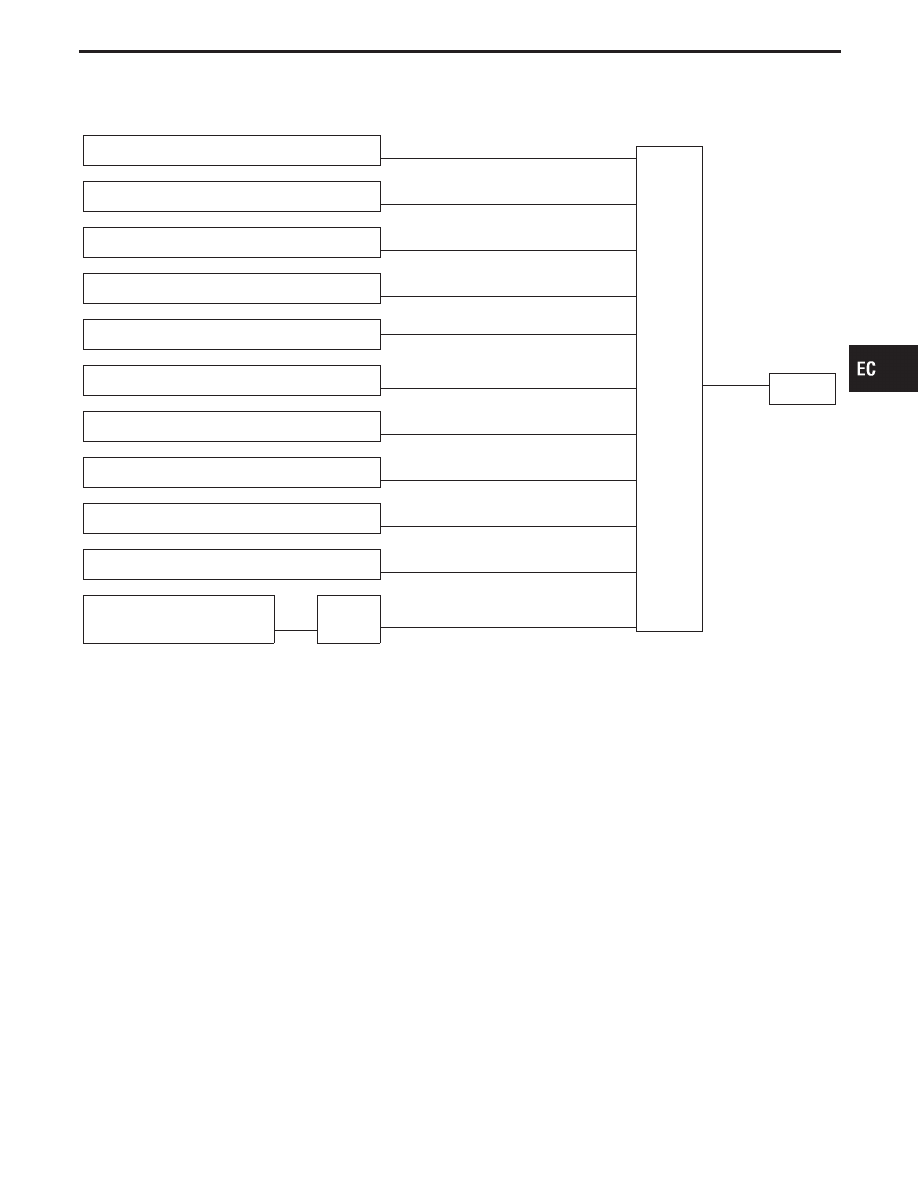
INPUT/OUTPUT SIGNAL LINE
Camshaft position sensor
E
Engine speed and piston position
ECM
E
Injector
Mass air flow sensor
E
Amount of intake air
Engine coolant temperature sensor
E
Engine coolant temperature
Heated oxygen sensor 1 (front)
E
Density of oxygen in exhaust gas
Throttle position sensor
E
Throttle position
Throttle valve idle position
PNP switch (TCM)
E
Park/Neutral position
Vehicle speed sensor
E
Vehicle speed
Ignition switch
E
Start signal
Battery
E
Battery voltage
Heated oxygen sensor 2 (rear)*
E
Density of oxygen in exhaust gas
Secondary throttle position
sensor
E
TAC
module
E
Secondary throttle valve opening angle
*: Under normal conditions, this sensor is not used to control the engine system.
BASIC MULTIPORT FUEL INJECTION
SYSTEM
The amount of fuel injected from the fuel injector is
determined by the ECM. The ECM controls the
length of time the valve remains open (injection
pulse duration). The amount of fuel injected is a
program value in the ECM memory. The program
value is preset by engine operating conditions.
These conditions are determined by input signals
(for engine speed and intake air) from both the cam-
shaft position sensor and the mass air flow sensor.
VARIOUS FUEL INJECTION
INCREASE/DECREASE COMPENSATION
The amount of fuel injected is compensated for to
improve engine performance. This will be made
under various operating conditions as listed below.
<Fuel increase>
I
During warm-up
I
When starting the engine
I
During acceleration
I
Hot-engine operation
I
When selector lever is changed from “N” to “D”
I
High-load, high-speed operation
<Fuel decrease>
I
During deceleration
I
During high speed operation
I
Extremely high engine coolant temperature
I
During TCS operation
I
During high engine speed operation
GI
MA
EM
LC
FE
AT
PD
FA
RA
BR
ST
RS
BT
HA
EL
IDX
ENGINE AND EMISSION BASIC CONTROL SYSTEM DESCRIPTION
EC-21