Infiniti Q45 (FY33). Manual - part 124


  Index      Infiniti     Infiniti Q45 (FY33) - service repair manual 2001 year


Search            copyright infringement  


Content   ..  122  123  124  125   ..


Infiniti Q45 (FY33). Manual - part 124


Fuel Cut Control (at no load & high engine
speed)

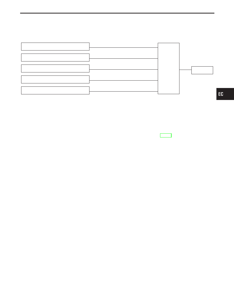
INPUT/OUTPUT SIGNAL LINE

Vehicle speed sensor

E

Vehicle speed

ECM

E

Injectors

PNP switch (TCM)

E

Park/Neutral position

Throttle position sensor

E

Throttle position

Engine coolant temperature sensor

E

Engine coolant temperature

Camshaft position sensor

E

Engine speed and piston position

If the engine speed is above 1,400 rpm with no load (for example,
in neutral and engine speed over 1,400 rpm) fuel will be cut off after
some time. The exact time when the fuel is cut off varies based on
engine speed.
Fuel cut will operate until the engine speed reaches 1,000 rpm,
then fuel cut is cancelled.
NOTE:
This function is different than deceleration control listed
under multiport fuel injection on EC-21.

GI

MA

EM

LC

FE

AT

PD

FA

RA

BR

ST

RS

BT

HA

EL

IDX

ENGINE AND EMISSION BASIC CONTROL SYSTEM DESCRIPTION

EC-25

Description

SEF523Y

The evaporative emission system is used to reduce hydrocarbons
emitted into the atmosphere from the fuel system. This reduction
of hydrocarbons is accomplished by activated charcoals in the
EVAP canister.
The fuel vapor in the sealed fuel tank is led into the EVAP canis-
ter which contains activated carbon. This is where the vapor is
stored when the engine is not operating.
The vapor in the EVAP canister is purged by the air flowing through
the EVAP canister purge volume control valve which is controlled
by engine control module. When the engine operates, the flow rate
of vapor controlled by the EVAP canister purge volume control
valve is proportionally regulated as the air flow increases.
The EVAP canister purge control valve shuts off the vapor purge
line during decelerating and idling; under normal operating condi-
tions the valve is usually open.

SEF210U

Inspection

EVAP CANISTER

Check EVAP canister as follows:
1.

Pinch the fresh air hose.

2.

Blow air into port

q

A

and check that it flows freely out of port

q

B

.

EVAPORATIVE EMISSION SYSTEM

EC-26

SEF231SA

TIGHTENING TORQUE

Tighten EVAP canister as shown in the figure.
Make sure new O-ring is installed properly between EVAP can-
ister and EVAP vent control valve.

SEF427N

SEF943S

FUEL TANK VACUUM RELIEF VALVE (Built into fuel
filler cap)

1.

Wipe clean valve housing.

2.

Check valve opening pressure and vacuum.

Pressure:

15.3 - 20.0 kPa (0.156 - 0.204 kg/cm

2

, 2.22 - 2.90

psi)

Vacuum:

−6.0 to −3.3 kPa (−0.061 to −0.034 kg/cm

2

, −0.87 to

−0.48 psi)

3.

If out of specification, replace fuel filler cap as an assembly.

CAUTION:

Use only a genuine fuel filler cap as a replacement. If an incor-
rect fuel filler cap is used, the MIL may come on.

EVAP CANISTER PURGE CONTROL VALVE

Refer to EC-488.

VACUUM CUT VALVE AND VACUUM CUT VALVE
BYPASS VALVE

Refer to EC-475.

EVAPORATIVE EMISSION (EVAP) CANISTER PURGE
VOLUME CONTROL VALVE

Refer to EC-444.

EVAPORATIVE EMISSION (EVAP) CANISTER PURGE
CONTROL SOLENOID VALVE

Refer to EC-488.

FUEL TANK TEMPERATURE SENSOR

Refer to EC-257.

GI

MA

EM

LC

FE

AT

PD

FA

RA

BR

ST

RS

BT

HA

EL

IDX

EVAPORATIVE EMISSION SYSTEM

Inspection (Cont’d)

EC-27

SEF462UA

EVAP SERVICE PORT

Positive pressure is delivered to the EVAP system through the
EVAP service port. If fuel vapor leakage in the EVAP system
occurs, use a leak detector to locate the leak.

SEF200U

PEF658U

HOW TO DETECT FUEL VAPOR LEAKAGE

CAUTION:

I

Never use compressed air or a high pressure pump.

I

Do not start engine.

I

Do not exceed 4.12 kPa (0.042 kg/cm

2

, 0.6 psi) of pressure

in EVAP system.

NOTE:

I

Improper installation of adapter to the service port may
cause a leak.

1.

Attach the EVAP service port adapter securely to the
EVAP SERVICE port.

2.

Also attach the pressure pump and hose.

3.

Turn ignition switch “ON”.

4.

Select the “EVAP SYSTEM CLOSE” of “WORK SUP-
PORT MODE” with CONSULT-II.

5.

Touch “START”. A bar graph (Pressure indicating dis-
play) will appear on the screen.

6.

Apply positive pressure to the EVAP system until the
pressure indicator reaches the middle of the bar graph.

7.

Remove adapter and hose with pressure pump.

8.

Locate the leak using a leak detector. Refer to “Evapo-
rative Emission Line Drawing”, EC-29.

SEF598U

SEF599U

------------------------------------------------------------------------------------------------------------------------------------------------------------------------------------------------------------------------------------------------------ OR ------------------------------------------------------------------------------------------------------------------------------------------------------------------------------------------------------------------------------------------------------

1.

Attach the adapter securely to the EVAP service port
and pressure pump with pressure gauge to the EVAP
service port.

2.

Apply battery voltage to between the terminals of both
EVAP canister vent control valve and vacuum cut valve
bypass valve to make a closed EVAP system.

3.

To locate the leak, deliver positive pressure to the EVAP
system until pressure gauge points reach 1.38 to 2.76
kPa (0.014 to 0.028 kg/cm

2

, 0.2 to 0.4 psi).

4.

Remove adapter and hose with pressure pump.

5.

Locate the leak using a leak detector. Refer to “Evapo-
rative Emission Line Drawing”, EC-29.

EVAPORATIVE EMISSION SYSTEM

Inspection (Cont’d)

EC-28


Content   ..  122  123  124  125   ..