Infiniti Q45 (FY33). Manual - part 47
Diagnostic Procedure 1
SYMPTOM:
Selector lever cannot be moved from “P” position when apply-
ing brake pedal. It can be moved when releasing brake pedal.
Selector lever can be moved from “P” position when key is
removed from key cylinder.
SAT118JA
SAT119JA
SAT393J
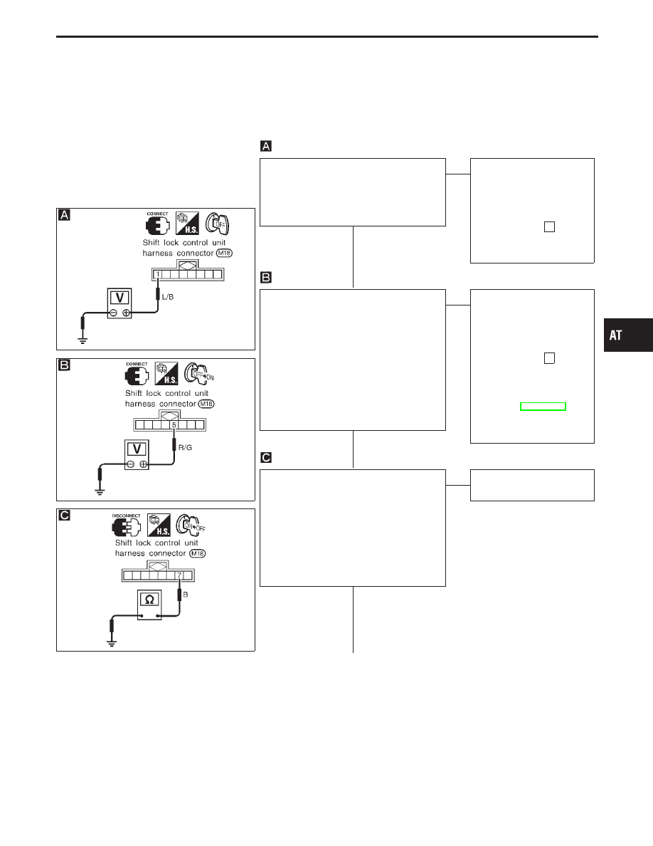
CHECK POWER SOURCE.
1. Turn ignition switch to “OFF” position.
2. Check voltage between shift lock control
unit harness terminal
q
1
and ground.
Battery voltage should exist.
OK
E
NG
Check the following items:
1. Harness for short or
open between battery
and shift lock control unit
harness terminal
q
1
2. 20A fuse [No.
26
,
located in the fuse block
(J/B)]
CHECK IGNITION SIGNAL.
1. Turn ignition switch to “OFF” position.
2. Check voltage between shift lock control
unit harness terminal
q
5
and ground.
0V
3. Turn ignition switch from “OFF” to “ON”
position.
(Do not start engine.)
4. Check voltage between shift lock control
unit harness terminal
q
5
and ground.
Battery voltage should exist.
OK
E
NG
Check the following items:
1. Harness for short or
open between battery
and shift lock control unit
harness terminal
q
5
2. 10A fuse [No.
17
,
located in the fuse block
(J/B)]
3. Ignition switch
Refer to EL section
(“POWER SUPPLY
ROUTING”).
CHECK GROUND CIRCUIT FOR CON-
TROL UNIT.
1. Turn ignition switch from “ON” to “OFF”
position.
2. Disconnect shift lock control unit har-
ness connector.
3. Check continuity between shift lock con-
trol unit harness terminal
q
7
and ground.
Continuity should exist.
OK
E
NG
Repair harness or connec-
tor.
q
A
GI
MA
EM
LC
EC
FE
PD
FA
RA
BR
ST
RS
BT
HA
EL
IDX
TROUBLE DIAGNOSES — A/T Shift Lock System
H
H
H
AT-185