Infiniti Q45 (FY33). Manual - part 48
 

  Index      Infiniti     Infiniti Q45 (FY33) - service repair manual 2001 year


Search            copyright infringement  


Content   ..  46  47  48  49   ..


Infiniti Q45 (FY33). Manual - part 48


Diagnostic Procedure 2

SYMPTOM:
Ignition key cannot be removed when selector lever is set to
“P” position. It can be removed when selector lever is set to
any position except “P”.

SAT118JB

SAT744J

SAT393J

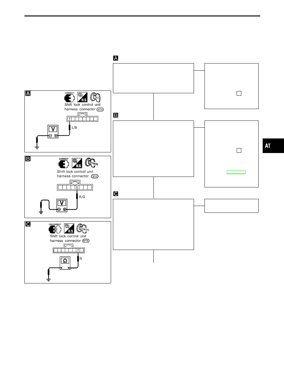
CHECK POWER SOURCE.
1. Turn ignition switch to “OFF” position.

2. Check voltage between shift lock control

unit harness terminal

q

1

and ground.

Battery voltage should exist.

OK

E

NG

Check the following items:
1. Harness for short or

open between battery
and shift lock control unit
harness terminal

q

1

2. 20A fuse [No.

26

,

located in the fuse block
(J/B)]

CHECK IGNITION SIGNAL.
1. Turn ignition switch to “OFF” position.

2. Check voltage between shift lock control

unit harness terminal

q

5

and ground.

0V

3. Turn ignition switch from “OFF” to “ON”

position (Do not start engine).

4. Check voltage between shift lock control

unit harness terminal

q

5

and ground.

Battery voltage should exist.

OK

E

NG

Check the following items:
1. Harness for short or

open between battery
and shift lock control unit
harness terminal

q

5

2. 10A fuse [No.

17

,

located in the fuse block
(J/B)]

3. Ignition switch

Refer to EL section
(“POWER SUPPLY
ROUTING”).

CHECK GROUND CIRCUIT FOR CON-
TROL UNIT.
1. Turn ignition switch from “ON” to “OFF”

position.

2. Disconnect shift lock control unit har-

ness connector.

3. Check continuity between shift lock con-

trol unit harness terminal

q

7

and ground.

Continuity should exist.

OK

E

NG

Repair harness or connec-
tor.

q

A

GI

MA

EM

LC

EC

FE

PD

FA

RA

BR

ST

RS

BT

HA

EL

IDX

TROUBLE DIAGNOSES — A/T Shift Lock System

H

H

H

AT-189

SAT394J

SAT936E

SAT399J

q

A

CHECK INPUT SIGNAL
(KEY SWITCH).
1. Reconnect shift lock control unit harness

connector.

2. Remove key from ignition switch.

When ignition key cannot be
removed, even if selector lever is in
“P” position, use emergency button.

3. Check voltage between A/T device har-

ness terminal

q

5

and ground.

0V

OK

E

NG

Check key switch.
(Refer to “Component
Check”, AT-194.)

1. Insert key into ignition switch.

2. Check voltage between A/T device har-

ness terminal

q

5

and ground.

Battery voltage should exist.

OK

E

NG

Check the following items:
1. Harness for short or

open between A/T device
harness terminal

q

5

and

key switch harness termi-
nal

q

4

2. Harness for short or

open between key switch
harness terminal

q

3

and

10A fuse [No.

28

,

located in the fuse block
(J/B)]

3. Key switch (Refer to

“Component Check”,
AT-194.)

CHECK INPUT SIGNAL
(DETENTION SWITCH - KEY).
1. Turn ignition switch from “OFF” to “ON”

position.
(Do not start engine.)

2. Set selector lever in “P” position and

release selector lever button.

3. Check voltage between shift lock control

unit harness terminal

q

2

and ground.

0V

OK

E

NG

Check detention switch
- key.
(Refer to “Component
Check”, AT-193.)

q

B

TROUBLE DIAGNOSES — A/T Shift Lock System

Diagnostic Procedure 2 (Cont’d)

H

H

H

H

AT-190

SAT128JA

SAT129JA

SAT599I

SAT274IB

SAT400J

q

B

CHECK INPUT SIGNAL
(DETENTION SWITCH - KEY).
1. Turn ignition switch to “ON” position.

(Do not start engine.)

2. Check voltage between shift lock con-

trol unit harness terminal

q

2

and

ground with brake pedal depressed
and selector lever button pushed.
Battery voltage should exist.

3. Check voltage between shift lock con-

trol unit harness terminal

q

2

and

ground with selector lever set in any
position except “P”.
Battery voltage should exist.

OK

E

NG

Check the following items:
1. Harness for short or open

between shift lock control
unit harness terminal

q

2

and detention switch har-
ness terminal

q

7

2. Harness for short or open

between detention switch
harness terminal

q

5

and

key switch harness terminal

q

4

3. Detention switch - key

(Refer to “Component
Check”, AT-193.)

1. Set selector lever in “P” position and

release selector lever button.

2. Turn ignition switch from “ON” to

“OFF” position.

CHECK OUTPUT SIGNAL
(KEY LOCK SIGNAL).
3. Turn ignition switch from “OFF” to

“ON” position.
(Do not start engine.)

4. Check voltage between key lock sole-

noid harness terminal

q

2

and ground

at the moment ignition key is turned
from “OFF” to “ON”.
Battery voltage should exist for
approximately 0.1 seconds.

OK

E

NG

Check harness for short or
open between shift lock sole-
noid harness terminal

q

2

and

control unit harness terminal

q

8

.

OK

NG

Repair harness or
connector.

Replace control unit.

CHECK GROUND CIRCUIT FOR KEY
LOCK SOLENOID.
1. Turn ignition switch from “ON” to

“OFF” position.

2. Disconnect key lock solenoid harness

connector.

3. Check continuity between key lock

solenoid harness terminal

q

1

and

ground.
Continuity should exist.

OK

E

NG

Repair harness or connector.

INSPECTION END

GI

MA

EM

LC

EC

FE

PD

FA

RA

BR

ST

RS

BT

HA

EL

IDX

TROUBLE DIAGNOSES — A/T Shift Lock System

Diagnostic Procedure 2 (Cont’d)

H

H

H

H

H

H

AT-191

SAT131JB

Shift Lock Control Unit Inspection

I

Measure voltage between each terminal by following “SHIFT
LOCK CONTROL UNIT INSPECTION TABLE”.

I

Pin connector terminal layout.

Shift Lock Control Unit Inspection Table

(Data are reference values.)

Terminal No.

Item

Condition

Judgment standard

!

@

q

1

q

7

Power source

Battery voltage

q

2

Detention switch
(Key)

I

When the key is in key cylinder,
selector lever is in “P” position, and
selector lever button pushed.

I

When the key is in key cylinder,
selector lever is set in any position
except “P”, and selector lever button
released.

Battery voltage

Except above

0V

q

4

Detention switch
(Shift)

I

When the key is in key cylinder,
selector lever is in “P” position, and
selector lever button pushed.

I

When the key is in key cylinder,
selector lever is set in any position
except “P”, and selector lever button
released.

Battery voltage

Except above

0V

q

5

Ignition signal

Battery voltage

q

6

Shift lock signal

When selector lever is
set in “P” position and
brake pedal is depressed

Battery voltage

Except above

0V

q

8

Key lock signal

When ignition switch is turned from
LOCK, “OFF” or “ACC” to “ON”.

Battery voltage
(Approximately 0.1 seconds)

Except above

0V

TROUBLE DIAGNOSES — A/T Shift Lock System

AT-192


Content   ..  46  47  48  49   ..