Infiniti Q45 (FY33). Manual - part 14


  Index      Infiniti     Infiniti Q45 (FY33) - service repair manual 2001 year


Search            copyright infringement  


Content   ..  12  13  14  15   ..


Infiniti Q45 (FY33). Manual - part 14


O/D OFF indicator lamp

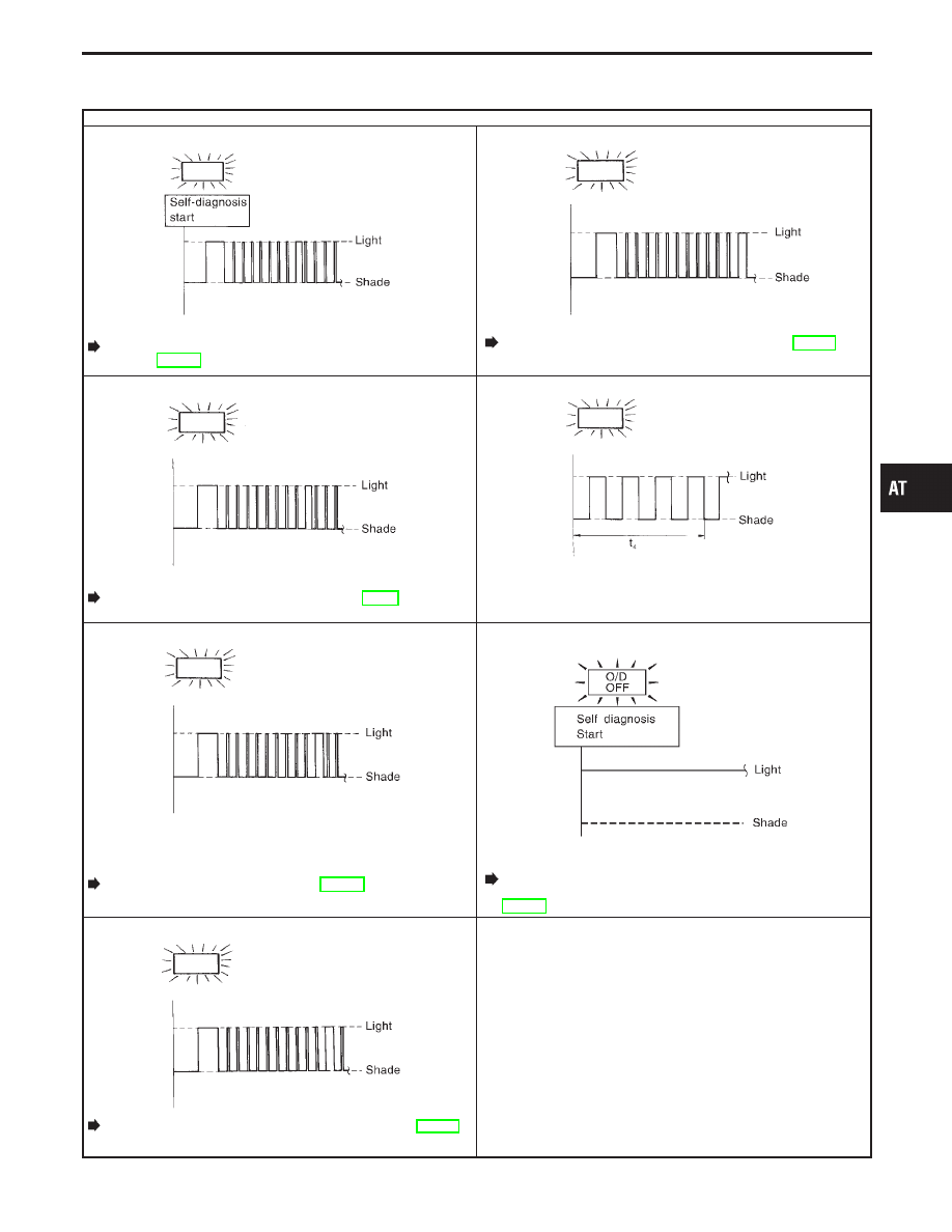
8th judgement flicker is longer than others.

SAT674I

A/T fluid temperature sensor is disconnected or TCM power
source circuit is damaged.

Go to A/T Fluid Temperature Sensor and TCM Power
Source, AT-147.

12th judgement flicker is longer than others.

SAT678I

The ECM-A/T communication line is open or shorted.

Go to A/T Communication Line (DTC: P0504), AT-157.

9th judgement flicker is longer than others.

SAT675I

Engine speed signal circuit is short-circuited or disconnected.

Go to Engine Speed Signal (DTC: 1207), AT-92.

Flickers as shown below.

SAT679I

Battery power is low.
Battery has been disconnected for a long time.
Battery is connected conversely.
(When reconnecting TCM connectors. — This is not a prob-
lem.)

10th judgement flicker is longer than others.

SAT676I

Turbine revolution sensor circuit is short-circuited or discon-
nected.

Go to Turbine Revolution Sensor, AT-154.

Lamp comes on.

SAT367J

PNP switch, overdrive control switch or throttle position switch
circuit is disconnected, or TCM is damaged.

Go to 21. TCM Self-diagnosis Does Not Activate (PNP,
Overdrive Control and Throttle Position Switches),
AT-177.

11th judgement flicker is longer than others.

SAT677I

Line pressure solenoid valve circuit is short-circuited or discon-
nected.

Go to Line Pressure Solenoid Valve (DTC: 1205), AT-125.

t

4

= 1.0 second

GI

MA

EM

LC

EC

FE

PD

FA

RA

BR

ST

RS

BT

HA

EL

IDX

ON BOARD DIAGNOSTIC SYSTEM DESCRIPTION

Diagnostic Procedure without CONSULT-II
(Cont’d)

AT-53

SAT631IA

SAT632I

SEF234G

Introduction

The TCM receives a signal from the vehicle speed sensor, throttle
position sensor or PNP switch and provides shift control or lock-up
control via A/T solenoid valves.
The TCM also communicates with the ECM by means of a signal
sent from sensing elements used with the OBD-related parts of the
A/T system for malfunction-diagnostic purposes. The TCM is
capable of diagnosing malfunctioning parts while the ECM can
store malfunctions in its memory.
Input and output signals must always be correct and stable in the
operation of the A/T system. The A/T system must be in good
operating condition and be free of valve seizure, solenoid valve
malfunction, etc.
It is much more difficult to diagnose a problem that occurs intermit-
tently rather than continuously. Most intermittent problems are
caused by poor electric connections or improper wiring. In this
case, careful checking of suspected circuits may help prevent the
replacement of good parts.
A visual check only may not find the cause of the problems. A road
test with CONSULT-II (or GST) or a circuit tester connected should
be performed. Follow the “Work Flow”. Refer to AT-58.
Before undertaking actual checks, take a few minutes to talk with
a customer who approaches with a driveability complaint. The cus-
tomer can supply good information about such problems, espe-
cially intermittent ones. Find out what symptoms are present and
under what conditions they occur. A “Diagnostic Worksheet” like the
example (AT-55) should be used.
Start your diagnosis by looking for “conventional” problems first.
This will help troubleshoot driveability problems on an electronically
controlled engine vehicle.
Also check related Service bulletins.

TROUBLE DIAGNOSIS — Introduction

AT-54

Diagnostic Worksheet

INFORMATION FROM CUSTOMER

KEY POINTS
WHAT 
........ Vehicle & A/T model
WHEN ........ Date, Frequencies
WHERE ..... Road conditions
HOW .......... Operating conditions, Symptoms

Customer name

MR/MS

Model & Year

VIN

Trans. model

Engine

Mileage

Incident Date

Manuf. Date

In Service Date

Frequency

l

Continuous

l

Intermittent

(

times a day)

Symptoms

l

Vehicle does not move.

(

l

Any position

l

Particular position)

l

No up-shift

(

l

1st

,

2nd

l

2nd

,

3rd

l

3rd

,

O/D)

l

No down-shift

(

l

O/D

,

3rd

l

3rd

,

2nd

l

2nd

,

1st)

l

Lockup malfunction

l

Shift point too high or too low.

l

Shift shock or slip

(

l

N

,

D

l

Lockup

l

Any drive position)

l

Noise or vibration

l

No kickdown

l

No pattern select

l

Others

(

)

O/D OFF indicator lamp

Blinks for about 8 seconds.

l

Continuously lit

l

Not lit

Malfunction indicator lamp (MIL)

l

Continuously lit

l

Not lit

GI

MA

EM

LC

EC

FE

PD

FA

RA

BR

ST

RS

BT

HA

EL

IDX

TROUBLE DIAGNOSIS — Introduction

AT-55

DIAGNOSTIC WORKSHEET

1.

l

Read the Fail-safe and listen to customer complaints.

AT-6

2.

l

CHECK A/T FLUID

AT-59

l

Leakage (Follow specified procedure)

l

Fluid condition

l

Fluid level

3.

l

Perform STALL TEST and LINE PRESSURE TEST.

AT-59, 62

l

Stall test — Mark possible damaged components/others.

l

Torque converter one-way clutch

l

Reverse clutch

l

Forward clutch

l

Overrun clutch

l

Forward one-way clutch

l

Low & reverse brake

l

Low one-way clutch

l

Engine

l

Line pressure is low

l

Clutches and brakes except high

clutch and brake band are OK

l

Line pressure test — Suspected parts:

4.

l

Perform all ROAD TEST and mark required procedures.

AT-64

4-1. Check before engine is started

AT-64

l

SELF-DIAGNOSTIC PROCEDURE — Mark detected items.

l

PNP switch, AT-81.

l

A/T fluid temperature sensor, AT-85.

l

Vehicle speed sensor

A/T (Revolution sensor), AT-89.

l

Engine speed signal, AT-92.

l

Torque converter clutch solenoid valve, AT-114.

l

Line pressure solenoid valve, AT-125.

l

Shift solenoid valve A, AT-129.

l

Shift solenoid valve B, AT-133.

l

Throttle position sensor, AT-137.

l

Overrun clutch solenoid valve, AT-143.

l

PNP, overdrive control and throttle position switches, AT-177.

l

A/T fluid temperature sensor and TCM power source, AT-147.

l

Vehicle speed sensor

MTR, AT-151.

l

Turbine revolution sensor, AT-154.

l

A/T communication line, AT-157.

l

Control unit (RAM), control unit (ROM), AT-160.

l

Battery

l

Others

4-2. Check at idle

AT-65

l

1. O/D OFF Indicator Lamp Does Not Come On, AT-162.

l

2. Engine Cannot Be Started In “P” And “N” Position, AT-163.

l

3. In “P” Position, Vehicle Moves Forward Or Backward When Pushed, AT-

163.

l

4. In “N” Position, Vehicle Moves, AT-164.

l

5. Large Shock. “N”

,

“R” Position, AT-165.

l

6. Vehicle Does Not Creep Backward In “R” Position, AT-166.

l

7. Vehicle Does Not Creep Forward In “D”, “2” Or “1” Position, AT-167.

4-3. Cruise test

AT-67,

AT-70

Part-1

l

8. Vehicle Cannot Be Started From D

1

AT-168.

l

9. A/T Does Not Shift: D

1

,

D

2

Or Does Not Kickdown: D

4

,

D

2

AT-169.

l

10. A/T Does Not Shift: D

2

,

D

3

AT-170.

l

11. A/T Does Not Shift: D

3

,

D

4

AT-171.

l

12. A/T Does Not Perform Lock-up, AT-172.

l

13. A/T Does Not Hold Lock-up Condition, AT-173.

l

14. Lock-up Is Not Released, AT-173.

l

15. Engine Speed Does Not Return To Idle (Light Braking D

4

,

D

3

), AT-174.

TROUBLE DIAGNOSIS — Introduction

Diagnostic Worksheet (Cont’d)

AT-56


Content   ..  12  13  14  15   ..