Infiniti M45 (Y34). Manual - part 147
TROUBLE DIAGNOSIS
ATC-73
C
D
E
F
G
H
I
K
L
M
A
B
ATC
SYSTEM DESCRIPTION
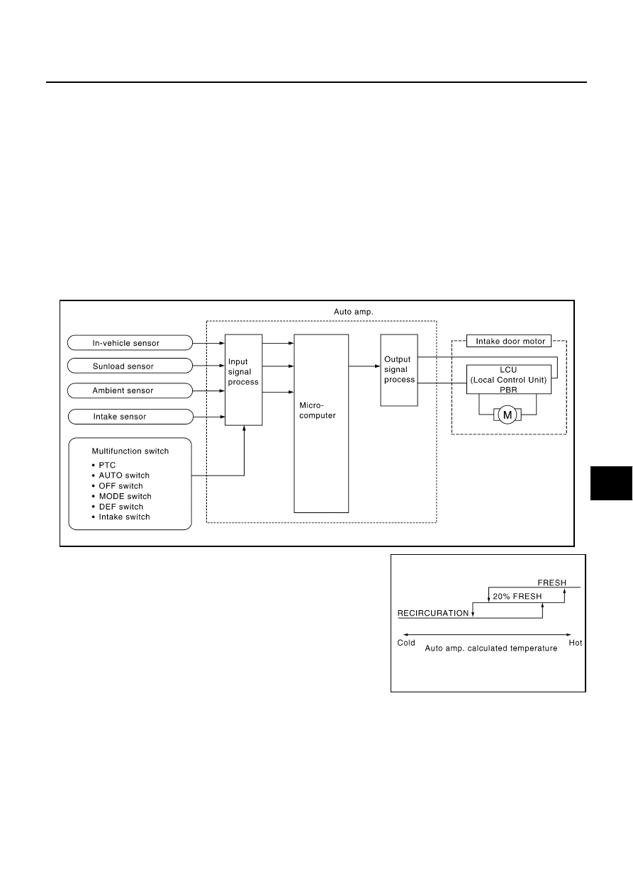
Component Parts
Intake door control system components are:
●
Auto amp.
●
Intake door motor
●
A/C LAN system (PBR built-in mode door motor, air mix door motor and intake door motor)
●
In-vehicle sensor
●
Ambient sensor
●
Sunload sensor
●
Intake sensor
System Operation
The intake door control determines intake door position based on the ambient temperature, the intake air tem-
perature and the in-vehicle temperature. When the ECON, DEFROST or OFF switches are pushed, the auto
amp. sets the intake door at the FRESH position.
Intake Door Control Specification
RJIA1291E
RHA383H