Infiniti M35/M45 Y50. Manual - part 782


  Index      Infiniti     Infiniti M35/M45 Y50 - service repair manual 2007 year


Search            copyright infringement  


Content   ..  780  781  782  783   ..


Infiniti M35/M45 Y50. Manual - part 782


FRONT SUSPENSION ASSEMBLY

FSU-25

[AWD]

C

D

F

G

H

I

J

K

L

M

A

B

FSU

THE ALIGNMENT PROCESS

IMPORTANT:
Use only the alignment specifications listed in this Service Manual.

When displaying the alignment settings, many alignment machines use “indicators”: (Green/red, plus or
minus, Go/No Go). Do NOT use these indicators.

The alignment specifications programmed into your machine that operate these indicators may not be cor-
rect.

This may result in an ERROR.

Some newer alignment machines are equipped with an optional “Rolling Compensation” method to “com-
pensate” the sensors (alignment targets or head units). DO NOT use this “Rolling Compensation”
method.

Use the “Jacking Compensation Method”. After installing the alignment targets or head units, raise the
vehicle and rotate the wheels 1/2 turn both ways.

See Instructions in the alignment machine you're using for more information on this.

INSPECTION OF CAMBER, CASTER AND KINGPIN INCLINATION ANGLES

Camber, caster, kingpin inclination angles cannot be adjusted.

Before inspection, mount front wheels onto turning radius gauge. Mount rear wheels onto a stand that has
same height so vehicle will remain horizontal.
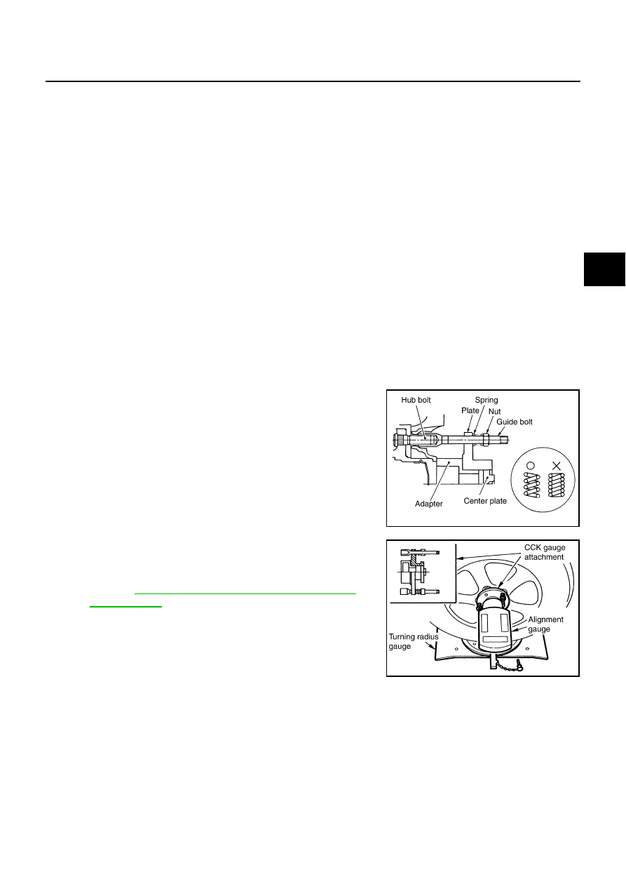
Using a CCK Gauge

Install the CCK gauge attachment [SST: KV991040S0 (

)] with the following procedure on wheel, then

measure wheel alignment.

1.

Remove three wheel nuts, and install the guide bolts to hub bolt.

2.

Screw the adapter into the plate until it contacts the plate tightly.

3.

Screw the center plate into the plate.

4.

Insert the plate assembly on the guide bolt. Put the spring in,
and then evenly screw the three guide bolt nuts. When fastening
the guide nuts, do not completely compress the spring.

5.

Place the dent of alignment gauge onto the projection of the
center plate and tightly contact them to measure.

CAUTION:

If camber, caster, or kingpin inclination angle is outside
the standard, check front suspension parts for wear and
damage. Replace suspect parts if a malfunction is
detected.

Kingpin inclination angle is reference value, no inspec-
tion is required.

SEIA0240E

Camber, caster, kingpin inclination angles:

Refer to 

FSU-37, "SERVICE DATA AND SPECIFICA-

TIONS (SDS)"

 .

SEIA0241E

FSU-26

[AWD]

FRONT SUSPENSION ASSEMBLY

Components

NES000IS

SEIA0665E

FRONT SUSPENSION ASSEMBLY

FSU-27

[AWD]

C

D

F

G

H

I

J

K

L

M

A

B

FSU

Removal and Installation 

NES000IT

REMOVAL

1.

Remove cowl top panel and hood. Refer to 

EI-18, "COWL TOP"

 , 

EI-17, "HOOD"

 .

2.

Install engine slinger, and then hoist engine. Refer to 

EM-119, "Removal and Installation (AWD Models)"

 .

3.

Remove tires from vehicle with a power tool.

4.

Remove wheel sensor from steering knuckle. Refer to 

BRC-54, "WHEEL SENSOR"

 .

CAUTION:

Do not pull on wheel sensor harness.

5.

Remove brake hose bracket. Refer to 

BR-11, "BRAKE TUBE AND HOSE"

 .

6.

Remove undercover with a power tool.

7.

Remove cotter pin (1), and then loosen the nut.

8.

Remove steering outer socket (2) from steering knuckle (3) so
as not to damage ball joint boot (4) using the ball joint remover
(suitable tool).

CAUTION:

Temporarily tighten the nut to prevent damage to threads
and to prevent the ball joint remover (suitable tool) from
suddenly coming off.

9.

Remove the mounting nut on the upper side of stabilizer con-
necting rod with a power tool, and then remove stabilizer con-
necting rod from transverse link.

10. Separate steering gear assembly and lower joint. Refer to 

PS-13, "STEERING COLUMN"

 .

11. Remove front cross bar. Refer to 

FSU-26, "Components"

 .

12. Remove steering hydraulic piping bracket from front suspension member. Refer to 

PS-39, "HYDRAULIC

LINE"

 .

13. Remove the mounting nut and bolt on the lower side of shock absorber arm with a power tool, and then

remove shock absorber arm from transverse link.

14. Remove cotter pin of transverse link and steering knuckle, and then loosen nut.

15. Remove transverse link from steering knuckle so as not to damage ball joint boot using the ball joint

remover (suitable tool).

CAUTION:

Temporarily tighten the nut to prevent damage to threads and to prevent ball joint remover (suit-
able tool) from suddenly coming off.

16. Set jack under front suspension member.

17. Remove the mounting nuts of engine mounting insulator. Refer to 

EM-114, "ENGINE ASSEMBLY"

 .

18. Remove the mounting bolts of member bracket, and then remove member bracket from front suspension

member with a power tool. Refer to 

FSU-26, "Components"

 .

19. Remove the mounting nuts of front suspension member with a power tool. Refer to 

FSU-26, "Compo-

nents"

 .

20. Gradually lower a jack to remove front suspension assembly from vehicle.

1.

Shock absorber mounting bracket

2.

Bound bumper

3.

Rubber seat

4.

Coil spring

5.

Shock absorber 

6.

Shock absorber arm

7.

Upper link

8.

Steering knuckle

9.

Transverse link

10. Steering stopper bracket

11. Washer

12. Stabilizer connecting rod

13. Stabilizer bar

14. Stabilizer bushing

15. Stabilizer clamp

16. Front suspension member

17. Front cross bar

18. Member bracket

19. Clamp

20. Cotter pin

21. Stopper rubber

Refer to 

GI-11, "Components"

 , for the symbols in the figure.

SGIA1183E

FSU-28

[AWD]

FRONT SUSPENSION ASSEMBLY

INSTALLATION

Installation is the reverse order of removal. For tightening torque, refer to 

FSU-26, "Components"

 .

Perform final tightening of each of parts (rubber bushing), under unladen conditions, which were removed
when removing front suspension assembly. Check wheel alignment. Refer to 

FSU-24, "Wheel Alignment

Inspection"

 .

Adjust neutral position of steering angle sensor after checking wheel alignment. Refer to 

BRC-6, "Adjust-

ment of Steering Angle Sensor Neutral Position"

 .

Check wheel sensor harness for proper connection. Refer to 

BRC-54, "WHEEL SENSOR"

 .


Content   ..  780  781  782  783   ..